Vehicle suspension

A vehicle and vehicle body technology, applied in vehicle components, suspension, elastic suspension, etc., can solve the problems of deterioration of vehicle vibration reduction performance, poor vibration reduction effect, limited vibration reduction effect, etc., and achieve the change of vehicle suspension stiffness coefficient and damping. The effect of coefficients

Inactive Publication Date: 2011-01-12
汪国胜
View PDF0 Cites 18 Cited by
  • Summary
  • Abstract
  • Description
  • Claims
  • Application Information

AI Technical Summary

Problems solved by technology

[0002] The current semi-active suspension of vehicles generally achieves the purpose of reducing vehicle vibration by adjusting the damping coefficient of the shock absorber to change the vibration characteristics of the vehicle suspension device. And the vibration damping effect is limited
Especially for large-tonnage military

Method used


Image

  • Vehicle suspension
  • Vehicle suspension
  • Vehicle suspension

Examples


Embodiment Construction

[0022] The specific embodiment of the present invention is described in detail below in conjunction with accompanying drawing:

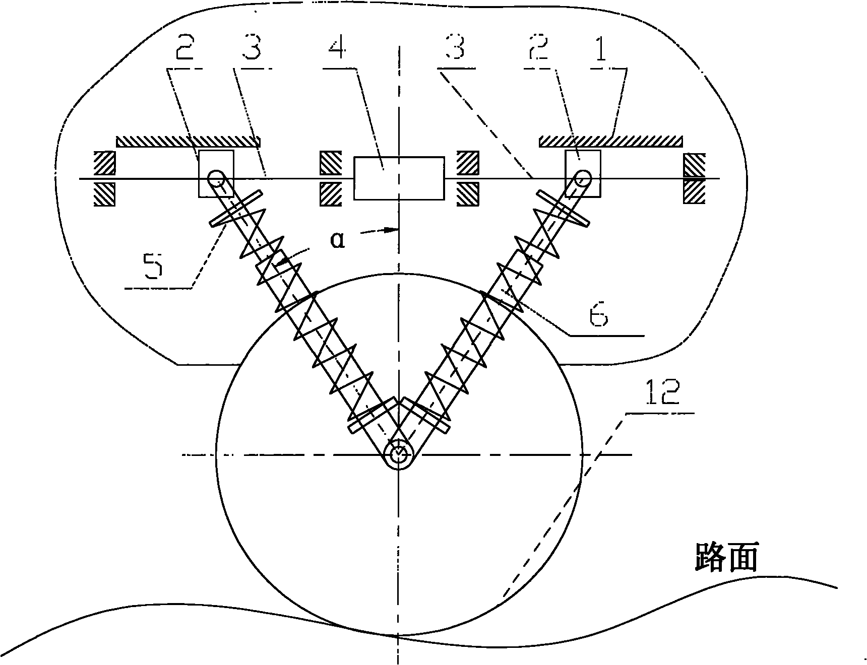
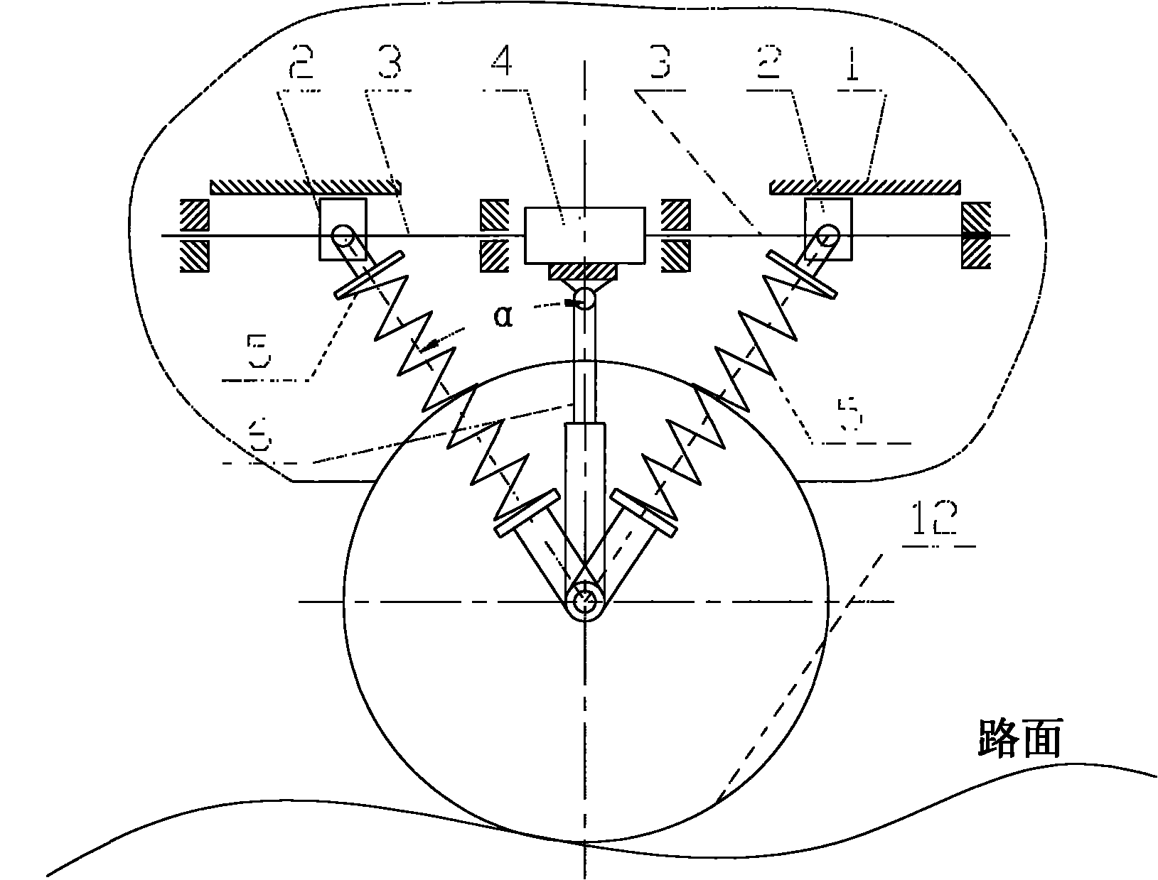
[0023] figure 1 It is a schematic diagram of the scheme of the present invention, such as figure 1 As shown, the vehicle suspension of the present invention includes a vehicle body 1, a nut 2, a screw rod 3, a motor 4, a spring 5, a shock absorber 6, a hub 7, and a wheel 12. It is characterized in that: each suspension assembly uses a motor 4 and two screw mechanisms arranged symmetrically; the rotating shaft of the motor 4 is coaxial with the screw rod 3 .

[0024] It is also characterized in that the suspension assembly is arranged in the front and back directions.

[0025] It is also characterized in that each suspension assembly uses two pairs of shock absorbers 6 and springs 5, each pair of shock absorbers 6 and springs 5 ​​are coaxial and axisymmetric, and the upper end is connected to the nut 2 of the screw mechanism with a pin, and the lower e


PUM


Abstract

The invention discloses a vehicle suspension, comprising upper cross arms 10, lower cross arms 11, hubs 7, springs 5, shock absorbers 6, a wheel 12 and other conventional spare parts. The vehicle suspension is characterized in that the suspension comprises a motor 4 and screw structures which are symmetrically arranged; the axis of rotation of the motor 4 is coaxial with screws 3 of the screw structures; and the screws 3 are driven to rotate by the motor 4. By starting the motor 4 to drive the screws 3 to rotate to change the front and back positions of nuts 2, the aims of adjusting the ground clearance of the vehicle and changing the stiffness coefficients of the springs in the vertical direction and the damping coefficients of the shock absorbers 6 in the vertical direction can be achieved, so that the vehicle adapts to the requirement of ride performance of travelling on different pavements at different speeds. Besides, the motionless posture of the vehicle can be adjusted by changing the height of the single suspension.

Description


Claims


Application Information

Patent Timeline
Owner 汪国胜
Why Eureka
Try Eureka