Sound insulation material, sound insulation system and manufacturing method of sound insulation material
A sound insulation material and sound insulation technology, which can be used in muffler devices, sound-producing equipment, instruments, etc., can solve problems such as vibration of sound insulation boards, and achieve the effect of high sound insulation performance and excellent sound insulation effect.
- Summary
- Abstract
- Description
- Claims
- Application Information
AI Technical Summary
Benefits of technology
Problems solved by technology
Method used
Image

Examples
no. 1 approach
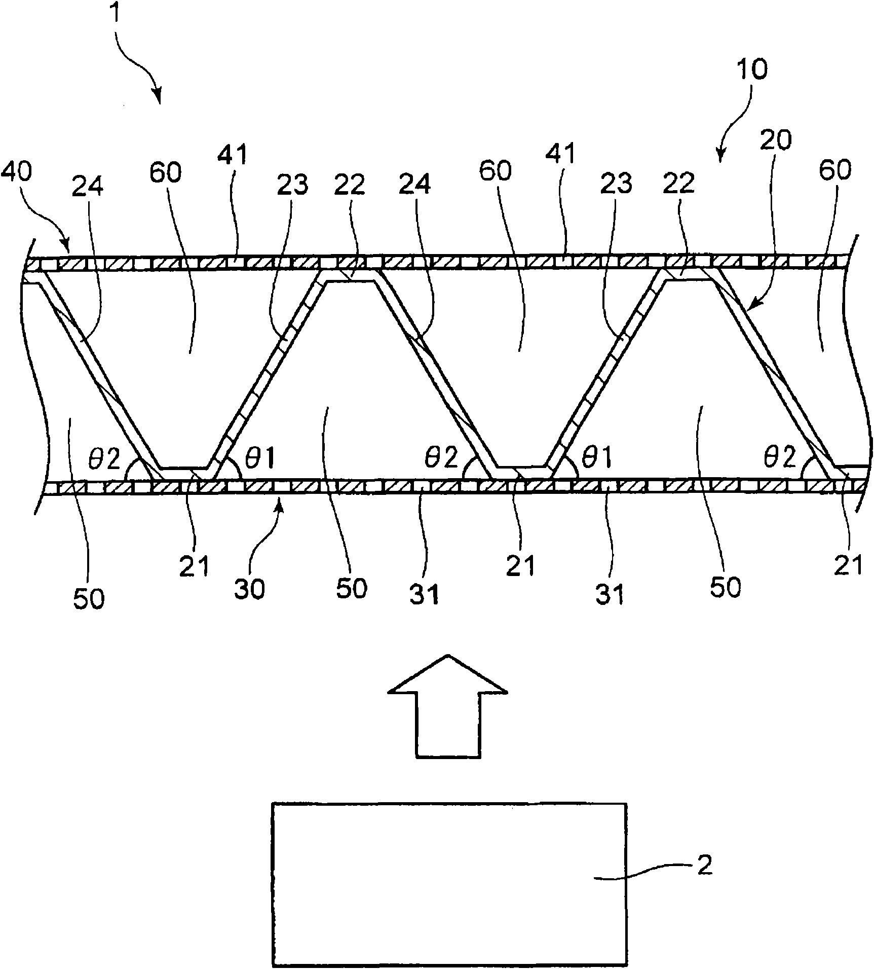
[0072] like figure 1 As shown, the sound insulation system 1 of the first embodiment is composed of a sound source 2 and a sound insulation material 10 arranged to face the sound source 2 .
[0073] The sound insulating material 10 has a sound insulating function for absorbing and blocking sound emitted from the sound source 2 . The sound-insulating material 10 has: a sound-shielding panel 20 continuous over the entire surface, a sound-source-side perforated plate 30 disposed closer to the sound source 2 than the sound-shielding panel 20 and having a plurality of sound-absorbing through-holes 31 , and a sound-shielding panel 20 interposed therebetween. The radiation-side perforated plate 40 having a plurality of through-holes 41 for reducing radiation sound is arranged on the side opposite to the sound source 2 (radiation side).
[0074] The perforated plates 30 and 40 are formed in flat plate shapes having the same plate thickness and opening shape, and are arranged in a postur
no. 2 approach
[0097] The sound insulating material of the sound insulating system of the second embodiment is configured to exhibit high sound insulating performance against a sound source such as a motor that emits a sound having a sharp peak at a specific frequency. In the sound insulating material, the volume ratio of the air layer is greater than 1, that is, the volume of the air layer on the sound source side is smaller than the volume of the air layer on the radiation side.
[0098] Specifically, as Figure 4 As shown, the sound insulating material 110 of this sound insulating system is equipped with the sound insulating board 120 which differs in structure from the sound insulating board 20 of the said 1st Embodiment.
[0099] The sound shielding board 120 has a some connection wall 123,124 which connects the adjacent junction part 21,22.
[0100] The connection wall 123 connects one end (the right end in the figure) of the sound source side joint part 21 and the other end (the left en
no. 3 approach
[0109] The sound insulation material of the sound insulation system of the third embodiment is configured to exhibit sufficient sound insulation performance for a sound source requiring sound insulation over a wide frequency band, such as a silencer. In this sound insulating material, the volume ratio of the air layer is less than 1, that is, the volume of the air layer on the emission side is smaller than the volume of the air layer on the sound source side.
[0110] Specifically, as Figure 8 As shown, the sound insulating material 310 of this sound insulating system has a sound insulating material 320 having a structure different from that of the sound insulating panel 20 of the above-mentioned first embodiment.
[0111] The sound shielding board 320 has a some connection wall 323,324 which connects the adjacent junction part 21,22.
[0112] The connection wall 323 connects one end (the right end in the figure) of the sound source side joint part 21 and the other end (the lef
PUM
 Abstract
Description
Claims
Application Information
 - R&D Engineer
- R&D Manager
- IP Professional
- Industry Leading Data Capabilities
- Powerful AI technology
- Patent DNA Extraction
Browse by: Latest US Patents, China's latest patents, Technical Efficacy Thesaurus, Application Domain, Technology Topic.
© 2024 PatSnap. All rights reserved.Legal|Privacy policy|Modern Slavery Act Transparency Statement|Sitemap