Connection fitting and application thereof

A technology for connecting accessories and connecting components, which is applied in the direction of connecting components, rods, mechanical equipment, etc., and can solve problems such as deformation, fracture, and device failure

Active Publication Date: 2011-06-15
SUN YAT SEN UNIV
View PDF4 Cites 2 Cited by
  • Summary
  • Abstract
  • Description
  • Claims
  • Application Information

AI Technical Summary

Benefits of technology

This new design allows for better control over fluid flow through an adapter used on equipment such as vehicles. It achieves this by allowing both connectors to move freely around their own center line during operation without being affected from any forces applied externally (such as gravity). When there's no significant movement outside), it remains securely attached even if some pressure acts upon them.

Problems solved by technology

The technical problem addressed in this patented text relates to providing flexible connectors that can withstand high levels of pressure without causing damage during use.

Method used


Image

  • Connection fitting and application thereof
  • Connection fitting and application thereof
  • Connection fitting and application thereof

Examples


Embodiment Construction

[0018] The present invention will be described in detail below in conjunction with the accompanying drawings.

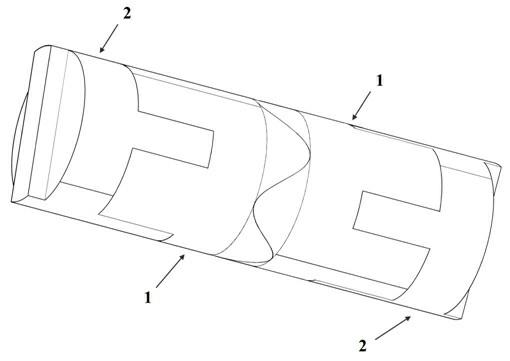
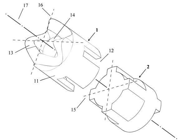
[0019] Such as figure 1 As shown, a connection fitting includes a cylindrical main body 11, a through hole 14 located at the central axis 17 of the main body 11, a groove 12 at one end of the main body, and a wavy curved surface 13 at the other end of the main body. One end of the main body 11 is distributed in a cross shape, and the wavy curved surface 13 is a curved surface generated by a periodically changing smooth curve, and has a plurality of crests and troughs evenly distributed; in this embodiment, a curved surface generated by a sinusoidal curve has a uniform Take the four peaks and troughs of the distribution as an example.

[0020] The ratio of the wave height to the wavelength within a sine cycle of the wavy surface 13 is 0.1 to 2.0; a groove cross reference line 15 corresponding to the cross-shaped groove 12 and a cross line 16 at the highest points of fou


PUM


Abstract

The invention discloses a connecting fitting which comprises a cylindrical main body, a through hole, a groove and a wavy curved surface structure, wherein the through hole is positioned at the central shaft of the main body; the groove is arranged at one end of the main body; and the wavy curved surface structure is arranged at the other end of the main body. The invention also discloses an application of the connecting fitting. In the application, two connecting fittings and two connecting assemblies are utilized, wherein each connecting assembly comprises a flange structure which is matched with the groove; the two connecting assemblies are connected in series through the two connecting fittings; the two connecting fittings are meshed through the wavy curved surfaces; and the two connecting assemblies are respectively connected to grooves which are at two ends of two connecting fittings through the flange structure. By utilizing the fitting provided by the invention, a device whichis poor in coaxial rotation angle is bad and has a self-adaptive capability to a horizontal force is formed, connected modules generate relative rotation under the condition that the connected modules are subjected to a limitation lateral force, and simultaneously the original angle difference can be recovered when the limitation lateral force vanishes.

Description


Claims


Application Information

Patent Timeline
Owner SUN YAT SEN UNIV
Why Eureka
Try Eureka