Sealing device and method of mounting same

A sealing device and sealing lip technology, used in valve devices, engine sealing, charging systems, etc., can solve the problems of difficult to pass through wire filters, intrusion into bearings, etc., and achieve excellent sealing performance and large initial interference. Effect

Active Publication Date: 2011-08-03
NOK CORP
View PDF7 Cites 3 Cited by
  • Summary
  • Abstract
  • Description
  • Claims
  • Application Information

AI Technical Summary

Benefits of technology

The inventive design allows for better sealability when used with certain materials like fluorspar® or polyimide (PI) due to its ability to prevent excess pressure from causing cracks during use without losing their strength overtime. This results in longer lifespan compared to traditional methods that only work well at low temperatures.

Problems solved by technology

The technical problem addressed in this patents relates to preventing unwanted particles or gases entering the bearings during operation when installing a sealed device around them.

Method used


Image

  • Sealing device and method of mounting same
  • Sealing device and method of mounting same
  • Sealing device and method of mounting same

Examples


Embodiment Construction

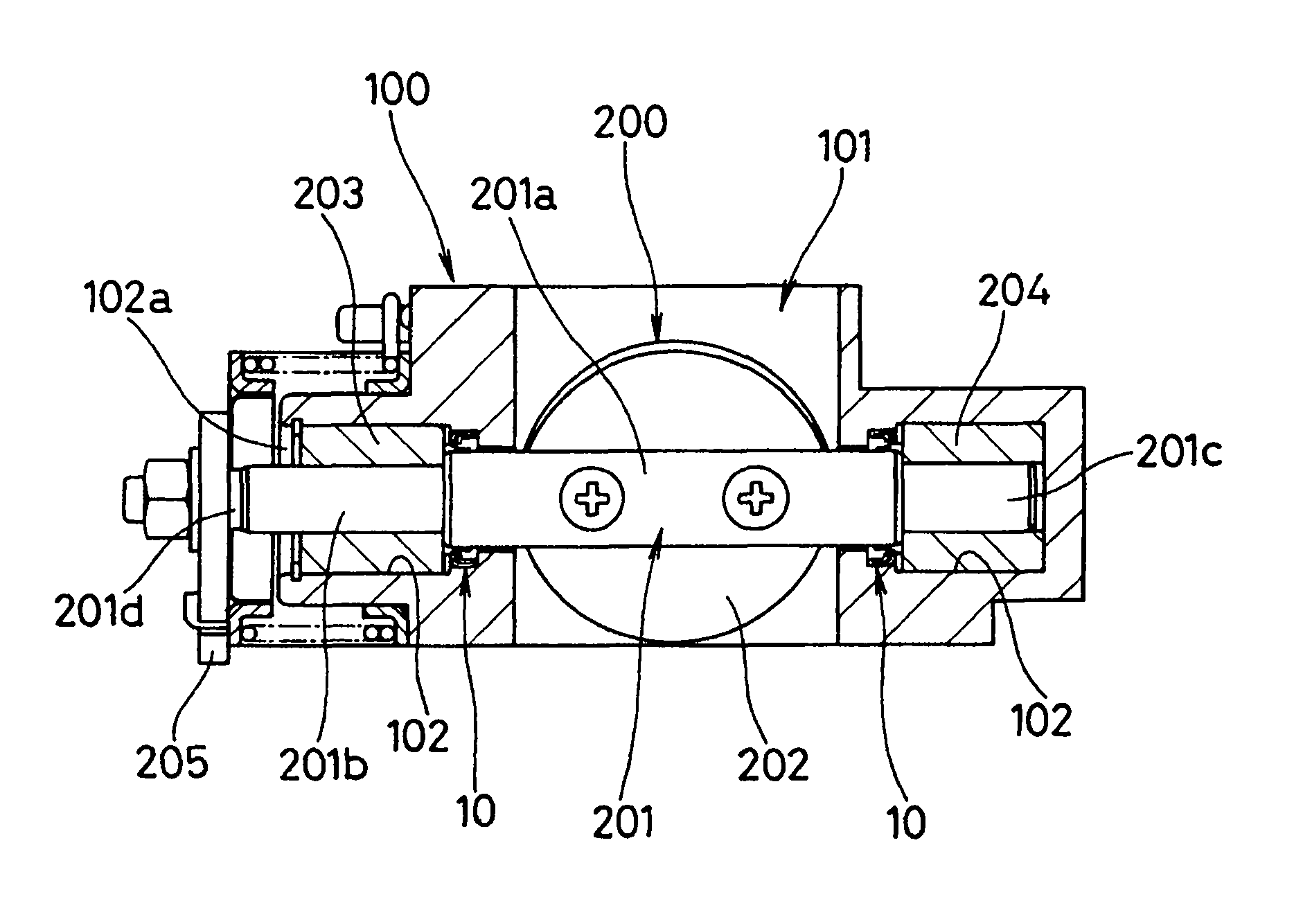
[0042] Preferred embodiments of the present invention will be described below with reference to the drawings. figure 1 It is an explanatory diagram showing the sealing device according to the present invention together with the valve assembly of the EGR system. figure 2 It is a sectional view of one side taken along a plane passing through the axis of the sealing device according to the present invention.

[0043] figure 1 The shown valve assembly includes: a housing 100 having a flow path 101 communicating with an exhaust manifold (not shown) and an intake manifold; and a butterfly valve 200 for adjusting the flow path cross-sectional area of ​​the flow path 101 .

[0044] Butterfly valve 200 is equipped with: valve shaft 201, is opened on the housing 100 in the direction perpendicular to the center line of flow path 101, and it is inserted in the valve shaft insertion hole 102 that one end is closed; Bearing 203,204, in the Both sides of the flow path 101 support the valve


PUM


Abstract

The invention relates to a sealing device and method of mounting the same. A sealing device (10) which seals, by means of a PTFE seal lip (13), the outer periphery of a valve shaft of a butterfly valve used for an EGR system of a vehicle. The sealing device (10) is provided with mounting rings (11, 12) press-fitted in and fixed to a valve shaft insertion hole (102), and also with the seal lip (13) held by the mounting rings (11, 12) and made to be in slidable contact with the outer peripheral surface of the valve shaft. The seal lip (13) is formed in a circular disc shape using a fluororesin, and an inner diameter section (13b) of the seal lip (13) is forcibly deformed by the valve shaft so as to face the flow path (101) side.

Description


Claims


Application Information

Patent Timeline
Owner NOK CORP
Why Eureka
Try Eureka