Power line carrier modulation method, demodulation method, circuit and chip

A technology of power line carrier wave and modulation method, applied in the field of power communication and communication, can solve the problems of power line noise environment change, inability to adapt to power line noise environment, restricting the quality of power line communication, etc., to achieve the effect of improving quality

Active Publication Date: 2011-09-21
QINGDAO EASTSOFT COMM TECH +1
View PDF6 Cites 15 Cited by
  • Summary
  • Abstract
  • Description
  • Claims
  • Application Information

AI Technical Summary

Benefits of technology

This technology helps reduce interference from electrical signals caused by fluctuations or changes over time due to factors like temperature variations. It also improves signal transmission even with varying levels of background radiation such as sunlight without causing any issues for data reception.

Problems solved by technology

This patented technical problem addressed in this patents relates to improving the reception of powerline communications over varying environmental conditions caused by various sources like interference from other electronic devices and changing noise levels on the electricity network itself due to factors like temporary connections between components being affected during operation.

Method used


Image

  • Power line carrier modulation method, demodulation method, circuit and chip
  • Power line carrier modulation method, demodulation method, circuit and chip
  • Power line carrier modulation method, demodulation method, circuit and chip

Examples


Embodiment Construction

[0035] In order to make the purpose, technical solutions and advantages of the embodiments of the present invention clearer, the technical solutions in the embodiments of the present invention will be clearly and completely described below in conjunction with the drawings in the embodiments of the present invention. Obviously, the described embodiments It is a part of embodiments of the present invention, but not all embodiments. Based on the embodiments of the present invention, all other embodiments obtained by persons of ordinary skill in the art without creative efforts fall within the protection scope of the present invention.

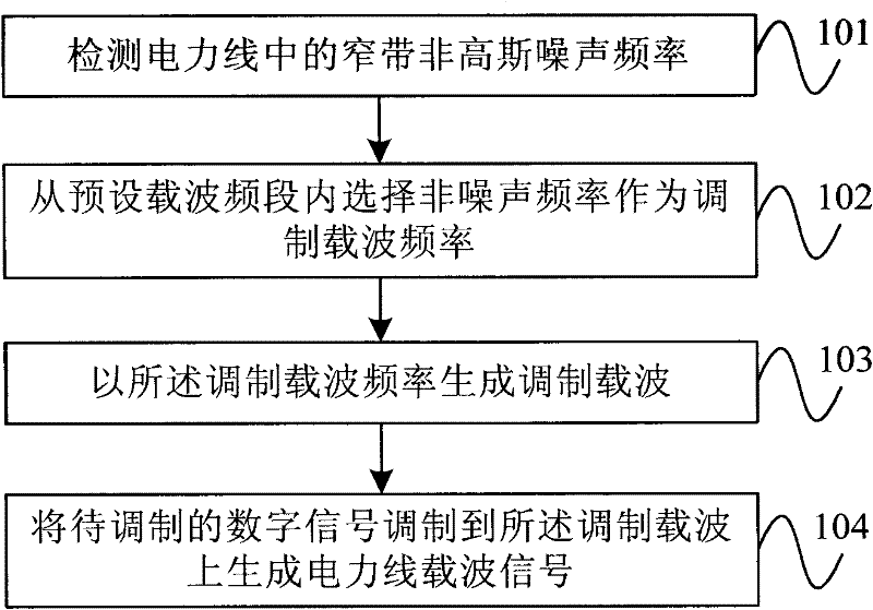
[0036] figure 2 It is a flow chart of an embodiment of the power line carrier modulation method according to the present invention. As shown in the figure, the method includes the following steps:

[0037] Step 101, detecting the frequency of narrow-band non-Gaussian noise in the power line.

[0038] Specifically, the frequency of narrow-band non-


PUM


Abstract

The invention provides a power line carrier modulation method, a demodulation method, a circuit and a chip. The modulation method comprises the following steps of: detecting narrow-band nongaussian noise frequency in a power line; selecting non-noise frequency from a preset carrier frequency band as modulation carrier frequency; generating a modulation carrier according to the modulation carrier frequency; modulating a digital signal to be modulated to the modulation carrier to generate a power line carrier signal. By using the modulation method, the narrow-band nongaussian noise frequency can be avoided, the change of noise environment of the power line can be adapted, and the quality of power line communication can be improved.

Description


Claims


Application Information

Patent Timeline
Owner QINGDAO EASTSOFT COMM TECH
Why Eureka
Try Eureka