Method for measuring phasor frequency of electric system

A technology of frequency measurement and power system, applied in the direction of frequency measurement devices, etc., can solve the problem of unsatisfactory frequency accuracy and achieve the effect of improving frequency calculation accuracy and meeting engineering needs

Active Publication Date: 2011-11-09
NARI TECH CO LTD
View PDF4 Cites 18 Cited by
  • Summary
  • Abstract
  • Description
  • Claims
  • Application Information

AI Technical Summary

Problems solved by technology

But these two methods also have some disadvantages
The M value necessary for calculating the phase by the method in [1] is als

Method used


Image

  • Method for measuring phasor frequency of electric system
  • Method for measuring phasor frequency of electric system
  • Method for measuring phasor frequency of electric system

Examples


Embodiment Construction

[0028] Assuming that the sequence of sampled values ​​after low-pass filtering by a finite-length impulse response digital low-pass filter is expressed as , where the frequency f is set to 35.7Hz, h=0,1,2,…. N takes 32, then for Second. The upper limit value of frequency measurement artificially set in advance and the lower limit 75Hz and 35Hz respectively.

[0029] Unless otherwise specified, the calculation variable is of double type, the unit of phase is radian, the unit of frequency is Hz, and the decimal truncation is rounded off.

[0030] Suppose the current sampling moment is ,but:

[0031] = -14.601629 , = -133.395520,

[0032] = = 1.679831

[0033] The recorded sampling instants are Time:

[0034] = 4.363731, = -134.115434,

[0035] = = 1.538271

[0036] Then the initial frequency value is:

[0037]

[0038] = 36.047874

[0039] The error between the initial frequency value and the actual frequency value is:

[0040] 36.0


PUM


Abstract

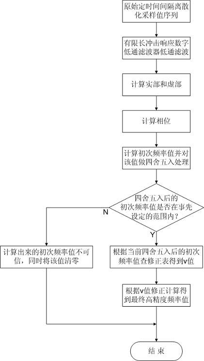
The invention relates to a method for measuring the phasor frequency of an electric system, which comprises the following steps of: performing low-pass filtering on the original fixed time interval discrete sampling value sequence by using a limited shock response digital low-pass filter to eliminate the interference of second and more harmonic components in the original input signal; respectively calculating a real part and an imaginary part of a sampling value sequence in previous 2T0 time starting from an ith sampling value, and calculating a phase according to a formula; and calculating the corrected current high-accuracy frequency value according to a formula. The method is not interfered by the reference level fluctuation of a power supply, is also applicable when the frequencies ofmultipath phasors of the electric system, which are connected to the same analog/digital (A/D) converter, are inconsistent, and cannot be continuously influenced by a previous calculated value; meanwhile, accuracy meets the actual requirement of engineering.

Description


Claims


Application Information

Patent Timeline
Owner NARI TECH CO LTD
Why Eureka
Try Eureka