fire extinguishing device

A technology of fire extinguishing device and buffer cavity, which is applied in fire rescue and other fields, can solve the problem that the fire extinguishing device has only a small recoil and no recoil, and achieves the effect of improving the safety of use and improving the fire extinguishing ability

Inactive Publication Date: 2011-12-28
SHAANXI LANDE SENMAO FIRE CONTROL TECH
View PDF11 Cites 0 Cited by
  • Summary
  • Abstract
  • Description
  • Claims
  • Application Information

AI Technical Summary

Benefits of technology

The inventor's new design improves upon existing designs by adding an extra space on top for storing energy during normal operation or when it needs to stop burning down quickly (referred to as 'micro-reflex'). This allows the system to perform better at stopping fires more effectively without being too sensitive towards external factors like wind pressure or temperature changes that could trigger flames).

Problems solved by technology

This technical problem addressed in this patented text relating to conventional supersonics fires that have limitations with regard to their ability to effectively suppress reboiling forces caused by increasing propulsive power during initial stages while also ensuring they can quickly return back towards normal operation once started again for effective cleaning purposes without causing damage.

Method used


Image

  • fire extinguishing device
  • fire extinguishing device
  • fire extinguishing device

Examples


Embodiment Construction

[0022] The technical solutions of the present invention will be further described in detail below through the accompanying drawings and embodiments.

[0023] In order to reduce the recoil generated by the action of the fire extinguishing device, the present invention is realized by improving the gas generator.

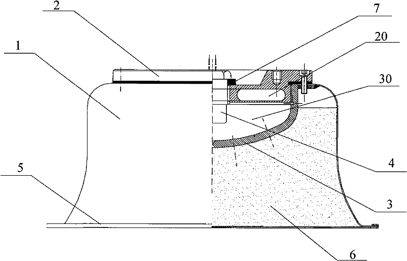
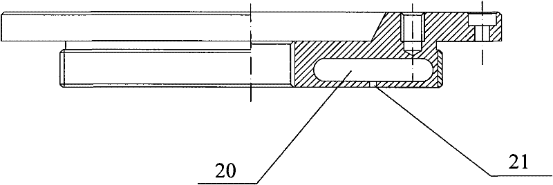
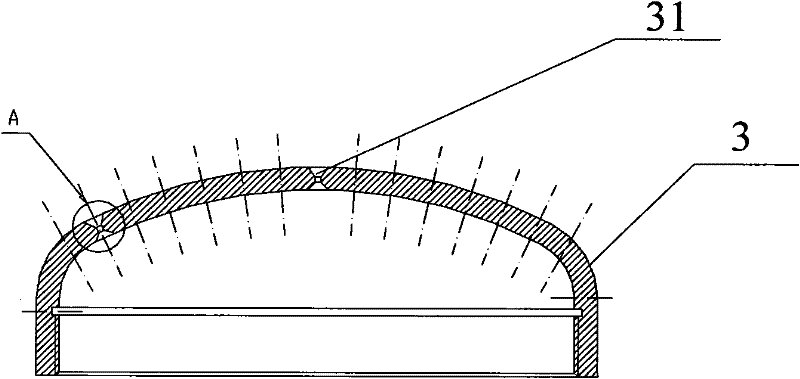
[0024] figure 1 It is a schematic diagram of the structure of the fire extinguishing device of the present invention. As shown in the figure, the fire extinguishing device of the present invention specifically includes: a casing 1, a top cover 2 and a porous member 3. The top cover 2 is fixed on the top of the casing 1, and the top cover 2 has Buffer chamber 20; The porous member 3 is fixed on the top cover 2 and is accommodated in the housing 1, and the combustion chamber 30 formed by the porous member 3 and the top cover 2 is in communication with the buffer chamber 20.

[0025] The present invention optimizes the structure of the top cover, and sets a buffer cavity in the top


PUM


Abstract

The invention relates to a fire extinguishing device. The fire extinguishing device comprises: a housing; a top cover, the top cover is fixed on the top of the housing, and there is a buffer cavity in the top cover; a porous member is fixed on the top Covered, accommodated in the housing, and the combustion chamber formed by the porous member and the top cover communicates with the buffer chamber; the gas generated by the combustion chamber enters the buffer chamber during operation, reducing recoil . The fire extinguishing device further includes: an initiator fixed on the top cover and accommodated in the cavity formed by the porous member and the top cover; a baffle plate sealed to the opening at the bottom of the casing. The buffer chamber communicates with the combustion chamber through the Laval hole. The buffer cavity is an annular cavity or several buffer cavities arranged concentrically in an annular shape or several buffer cavities arranged along the circumference. Therefore, the fire extinguishing device of the present invention utilizes the buffer chamber of the top cover to realize a slight recoil force, so the safety of use of the fire extinguishing device is improved, and the fire extinguishing ability can be further improved.

Description


Claims


Application Information

Patent Timeline
Owner SHAANXI LANDE SENMAO FIRE CONTROL TECH
Why Eureka
Try Eureka