Electrocardio-electrode placement positioning device
A positioning device and ECG electrode technology, applied in the field of public health, can solve the problems of unknown reliability of electrocardiogram diagnosis results, inapplicability and impracticality of electrocardiogram examination, etc.
- Summary
- Abstract
- Description
- Claims
- Application Information
AI Technical Summary
Problems solved by technology
Method used
Image

Examples
Embodiment 1
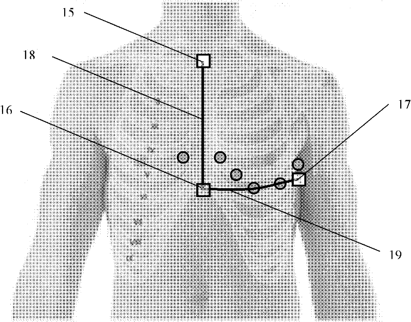
[0050] see figure 2 . An electrocardiographic electrode positioning device using a distance measurement method is characterized by an inverted T-shaped dressing tape connected by a longitudinal dressing tape 22 and a horizontal dressing tape 23 . There is a positioning hole 24 for placing the marker 16 at the lower border of the sternum at the connection between the longitudinal dressing tape 22 and the horizontal dressing tape 23, and a guide groove 25 for determining and placing the marker 15 at the upper border of the sternum on the upper part of the longitudinal dressing tape 22 A positioning ribbon 27 for locating the marker 15 on the upper edge of the sternum is attached to the application tape adjacent to the guide groove 25, and a positioning ribbon 28 for locating the V1 electrode 9 and the V2 electrode 10 is provided above the positioning hole 24. There are wedge-shaped notches 26 at both ends of the belt 23 for placing the axillary markers 17, and the horizontal appl
Embodiment 2
[0058] see image 3 . An ECG electrode positioning device using a reference picture projection method, comprising a suspension beam structure 41, a projector 42 is fixed on the suspension beam structure 41, a patient 40 lies on a platform 39, the suspension beam structure 41 is fixed on the platform 39, and the projector 42 is located at the place 30mm-100mm above the chest of the patient 40, and the projector 42 can be a general handheld projector, or a customized special instrument.
[0059] The microprocessor system in the projector 42 can project the pre-stored pictures onto the chest of the patient 40 to form a projection area 43, and a sheet is stored in the projector 42 that marks the chest measurement electrodes V1-V6, the upper edge of the sternum, and the substernal region. Reference pictures of margin and left midaxillary markers.
[0060] The projector 42 has adjustment functions for height, projection area displacement and stretching; the position and zoom ratio of
Embodiment 3
[0066] see Figure 4 . Similar to the reference picture positioning device in Embodiment 2, the ECG electrode positioning device using the spot projection method is composed of a suspension beam structure 41 and a spot projection device 44 installed thereon. The suspension beam structure can be moved up and down for height adjustment, and the spot projecting device 44 can move horizontally and vertically along the suspension beam structure 41 . The light spot projecting device 44 marks the light spots formed by directly projecting light on the chest surface of the patient 40 by directly projecting the light spots on the upper sternum, the lower sternum, the marker in the left axilla and the reference positions of the chest measurement electrodes V1-V6.
[0067] see Figure 5 . The spot projecting device 44 mainly comprises a light source power supply 45, a light source panel 46, a horizontal zoom lens 47, a vertical zoom lens 48 and adjustment devices 49, 50, and nine laser di
PUM
 Abstract
Description
Claims
Application Information
 - R&D Engineer
- R&D Manager
- IP Professional
- Industry Leading Data Capabilities
- Powerful AI technology
- Patent DNA Extraction
Browse by: Latest US Patents, China's latest patents, Technical Efficacy Thesaurus, Application Domain, Technology Topic.
© 2024 PatSnap. All rights reserved.Legal|Privacy policy|Modern Slavery Act Transparency Statement|Sitemap