Air bag restraint device with a plurality of inflating matters
An airbag device, inflatable technology, applied in the directions of pedestrian/occupant safety arrangement, vehicle safety arrangement, transportation and packaging, etc., can solve the problems of ineffective protection of the driver, technical difficulties, pressure drop, etc., to prevent explosion. Possibilities, simplifying the modular structure, expanding the effect of using space
- Summary
- Abstract
- Description
- Claims
- Application Information
AI Technical Summary
Problems solved by technology
Method used
Image


Examples
Embodiment 1
[0034] The airbag device disclosed in this embodiment has a plurality of inflatables, which can simultaneously protect the driver and the front passenger from the front. Bag assembly 100 .
[0035] see figure 1 , the air bag assembly 100 has two inflatables 110, 120 and a gas distribution chamber 200, an air inlet 130 is arranged on the air bag assembly 100, the gas distribution chamber 200 communicates with the air inlet 130, and the air inlet 130 is directly connected to the gas generator, of course, it can also be connected to the gas generator through the gas guiding device. The whole air bag assembly sewing process can be like this: first adopt the first gas distribution chamber bag sheet (not shown in the figure) and the second gas distribution chamber bag sheet (not shown in the figure) to sew the gas distribution chamber 200 . All sewing is carried out on a flat surface, which is easy to operate, convenient to control, and simple in process. Then the gas distribution
Embodiment 2
[0041] see Figure 9 , the safety airbag device is embedded in the front side of each rear passenger in the roof, and the airbag assembly 100a has two or three inflatables, wherein each inflatable is used to protect each rear passenger from the front, said The volume ratio of each air bag is the same. All the other structures are with embodiment 1.
Embodiment 3
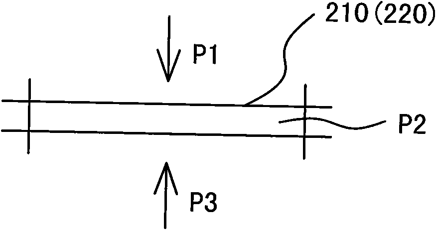
[0043] see Figure 7 , the airbag device is embedded in the roof, and the airbag components are arranged at intervals. The first vent bag assembly 100 is arranged at the front end of the roof, and has two inflatables 110, 120 and a gas distribution chamber 200 connected together, wherein one inflatable 110 is used to protect the driver from the front, and the other inflatable 120 Used to protect the front occupants from the front. The gas distribution chamber 200 is provided with two distribution outlet channels 210, 220, the distribution outlet channels 210, 220 are in a constricted state relative to the gas distribution chamber 200, the gas distribution channel 210 extends into the inflatable object 110 and connects with the inflatable object 110 is internally penetrated. The gas distribution channel 220 extends into the inflatable 120 and communicates with the inside of the inflatable 120 .
[0044] The air bag modules 100a of each row in the back are embedded in the roof,
PUM
 Abstract
Description
Claims
Application Information
 - R&D Engineer
- R&D Manager
- IP Professional
- Industry Leading Data Capabilities
- Powerful AI technology
- Patent DNA Extraction
Browse by: Latest US Patents, China's latest patents, Technical Efficacy Thesaurus, Application Domain, Technology Topic.
© 2024 PatSnap. All rights reserved.Legal|Privacy policy|Modern Slavery Act Transparency Statement|Sitemap