Wind, gas generator

A technology for power generation devices and wind power generators, applied in the direction of electromechanical devices, wind power generation, wind engines, etc., can solve the problems of discontinuous wind, unstable wind speed, large investment, etc., and achieve the effect of long flow time

Inactive Publication Date: 2008-05-28
李士明
View PDF0 Cites 0 Cited by
  • Summary
  • Abstract
  • Description
  • Claims
  • Application Information

AI Technical Summary

Benefits of technology

The technical feature described in this patented technology relates to improving the performance (power) of devices called generators. These machines have three parts - they include a wind motor, a compression mechanism, and a wind catching mechanism. By combining these components into multiple units, larger amounts of electrical power may be produced compared to just having them alone. Additionally, the generator allows for independent control over its output speed based upon factors like weather conditions such as rain and snow. Overall, this design makes generating large amount of clean renewed energy faster and easier than existing methods.

Problems solved by technology

This patented technical problem addressed by this patents relates to current methods for generating energy from natural sources like wind or water (wind) that are intermittently fluctuating with varying speeds due to weather conditions. These issues make it difficult to maintain continuous operation over long periods without expensive equipment being installed at significant expenses.

Method used


Image

  • Wind, gas generator
  • Wind, gas generator

Examples


Embodiment Construction

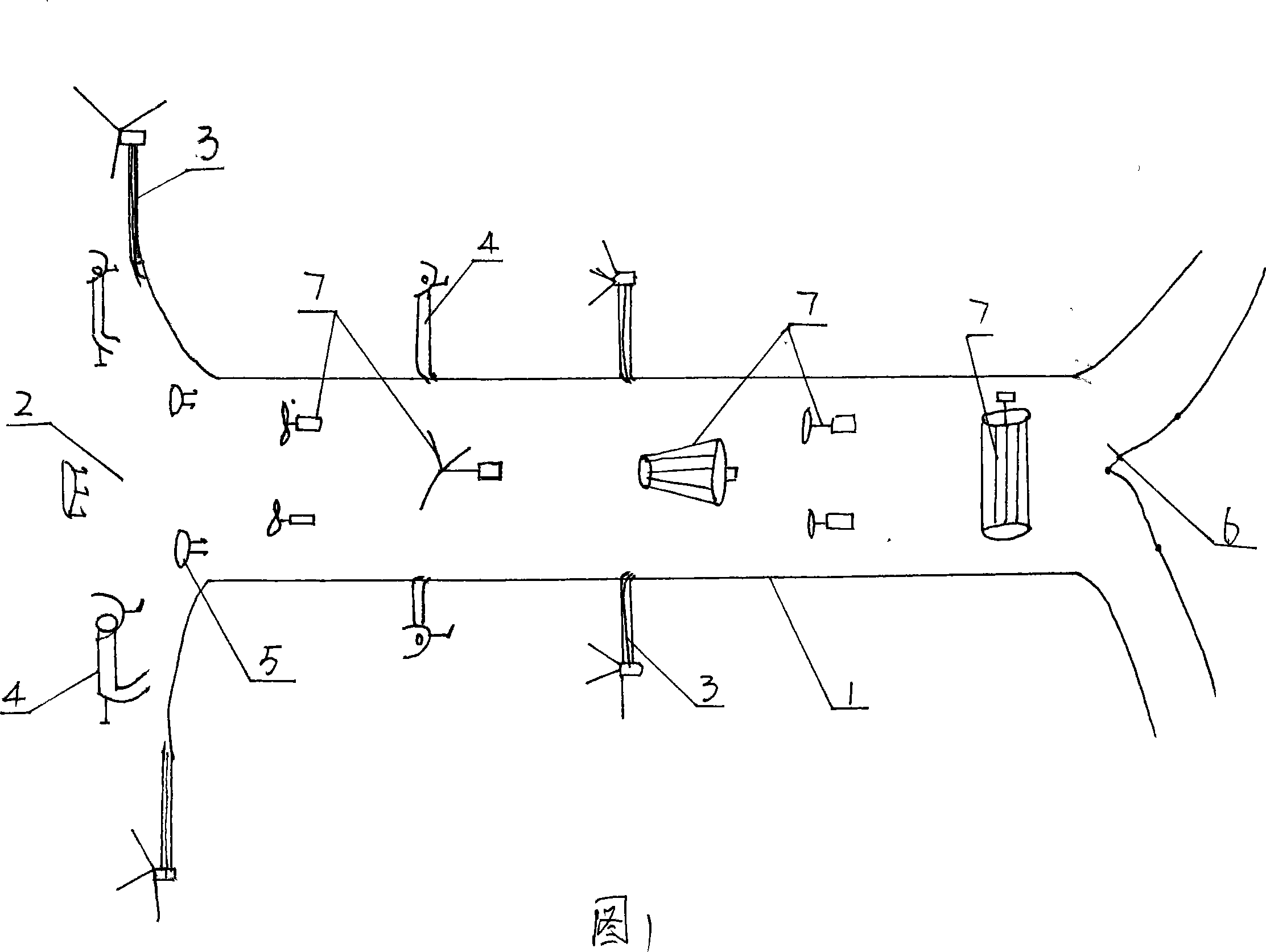
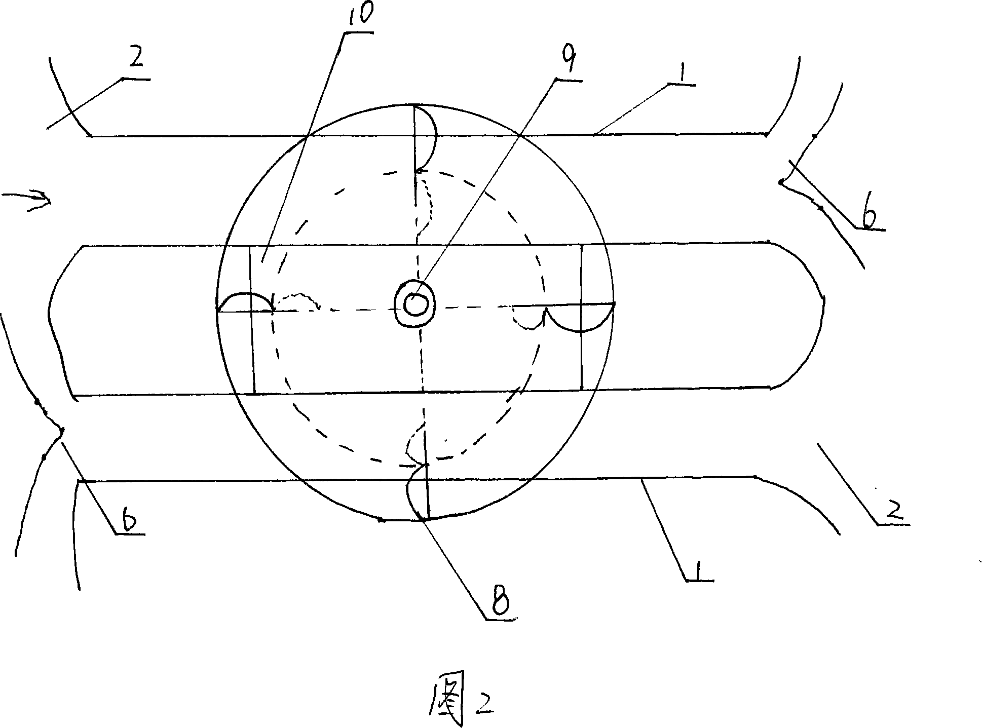
[0016] As shown in Figure 1, the wind and gas power generation device includes a wind power generator, which is characterized in that: a group of wind power generators 7 are installed in the pipeline 1 to form a wind and gas power generation device, on the air inlet 2 of the pipeline 1 or on the pipeline 1 Install wind compressor 3.

[0017] In the wind and gas power generation device of the present invention, a wind catcher 4 is installed on the air inlet 2 of the pipeline or the pipeline 1 .

[0018] In the wind and gas power generation device of the present invention, a blower 5 is installed in the pipeline 1 .

[0019] In the wind and gas power generation device of the present invention, the wind power generator 7 is a two-blade, three-blade, barrel-type, fan-type or drum-type wind power generator.

[0020] In the wind and gas power generation device of the present invention, the air inlet 2 of the pipeline 1 is a trumpet mouth, and the air outlet 6 of the pipeline 1 is a Y-


PUM


Abstract

The invention discloses a wind-air electricity generating system, comprising a wind-driven generator. The invention is characterized in that a set of wind-driven generator (7) is installed in the inner portion of a pipeline (1) to form the wind-air electricity generating system, and a wind compressor (3) is installed on the wind inlet (2) of the pipeline (1) or on the pipeline (1). The invention enables the electricity generating system to work around a clock through adopting the wind air fit, which increases the practicability of the electricity generating system, and reduces operation costs.

Description


Claims


Application Information

Patent Timeline
Owner 李士明
Why Eureka
Try Eureka