Filtering method for transformer oil

A technology of transformer oil and filtering method, which is applied in the direction of chemical instruments and methods, transformer/inductor cooling, filtration and separation, etc., which can solve problems such as troublesome operation, environmental pollution, oil leakage, etc., and achieve convenient oil filtering, short construction period, The effect of avoiding pollution

Inactive Publication Date: 2012-04-25
CHINA FIRST METALLURGICAL GROUP
View PDF3 Cites 5 Cited by
  • Summary
  • Abstract
  • Description
  • Claims
  • Application Information

AI Technical Summary

Benefits of technology

Inventions described by this inventor involve changing how much oil flows from one side into another without stopping or requiring filters that can get dirty quickly due to their repeated use over time. These improvements make it more efficient than traditional methods like turning off an engine when there're no longer needed. Additionally, they don’t require expensive equipment such as pumps or other components at every stage, making them cost-effective compared with older systems.

Problems solved by technology

There are technical problem addressed in this patented text that requires an improved way to complete transformer lubricating oil filtraction while avoiding having to stop or disconnect from other parts of the system altogether.

Method used


Image

  • Filtering method for transformer oil
  • Filtering method for transformer oil

Examples


Embodiment Construction

[0019] Embodiments of the present invention will be further described below in conjunction with the accompanying drawings.

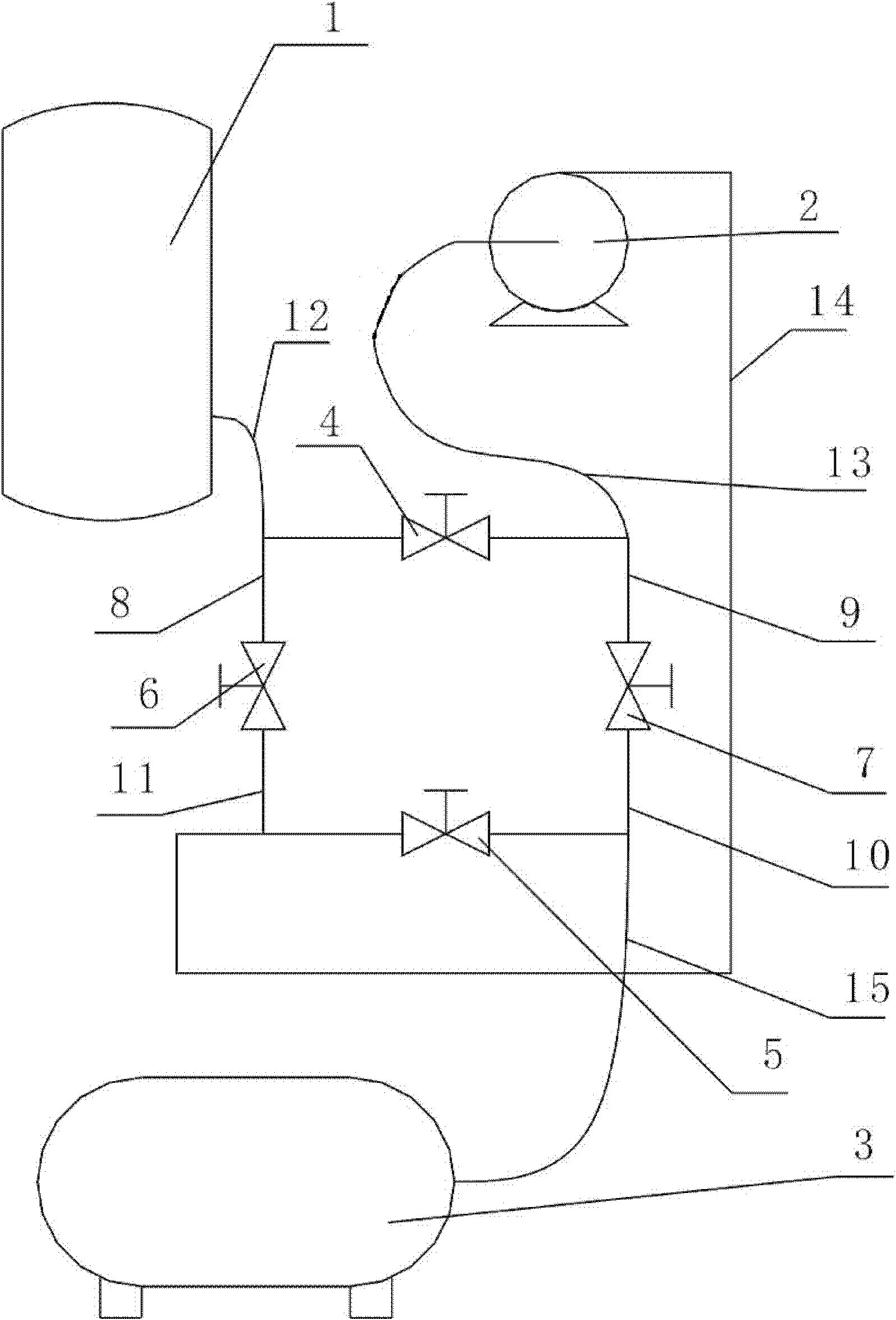
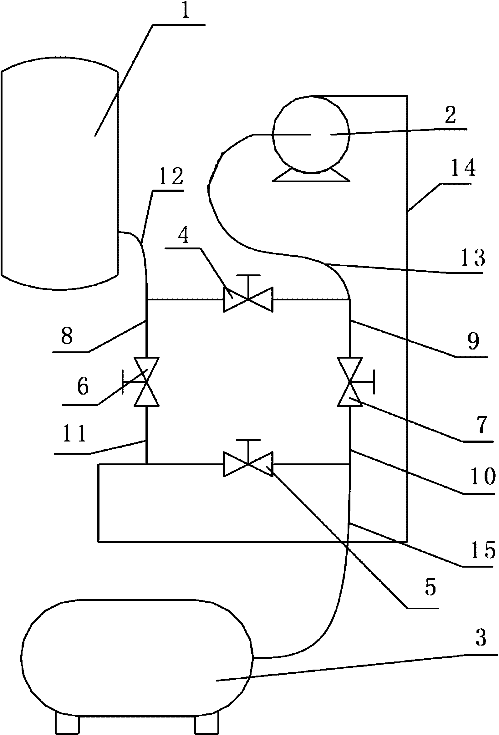
[0020] see figure 1 , the steps of a transformer oil filtering method are:

[0021] 1. Assemble the transformer oil filter auxiliary device.

[0022] One end of the first valve 4 is connected with one end of the fourth valve 7 through the second pipeline 9, the other end of the fourth valve 7 is connected with one end of the second valve 5 through the third pipeline 10, and the other end of the second valve 5 One end is connected to one end of the third valve 6 through the fourth pipeline 11, the other end of the third valve 6 is connected to the first valve 4 through the first pipeline 8, and the oil tank 1 of the transformer is connected to the first pipeline through the fifth pipeline 12. The oil return port of the oil filter unit 2 is connected with the second pipeline 9 through the sixth pipeline 13, and the oil outlet of the oil filter unit 2 is con


PUM


Abstract

The invention relates to a filtering method for transformer oil. The filtering method comprises the following steps of: firstly, sequentially connecting two ends of each of a first valve, a fourth valve, a second valve and a third value by pipelines to form a valve bank which is in an annular structure and respectively connecting a transformer oil tank, an oil return port of an oil filter, a first oil tank and an oil outlet of the oil filter; secondly, starting the oil filter for filtering oil in the transformer oil tank; and thirdly, pumping the filtered oil into the transformer oil tank. The filtering method has the beneficial effects that: firstly, the filtering method is simple in operation; and the oil filter is not needed to be closed in the filtering process, so that the work period is shortened and the efficiency is improved; secondly, devices adopted in the method are conventional devices, are low in price and are convenient for popularization and application; thirdly, the missing of oil products and the pollution to the environment are avoided; and fourthly, the filtering method is not only suitable for oil filtering occasions, but also is suitable for oil exchange and new oil injection occasions.

Description


Claims


Application Information

Patent Timeline
Owner CHINA FIRST METALLURGICAL GROUP
Why Eureka
Try Eureka