Conveying frying machine

Active Publication Date: 2013-07-18
CHUAN YANG FOODS MACHINE
View PDF11 Cites 3 Cited by
  • Summary
  • Abstract
  • Description
  • Claims
  • Application Information

AI Technical Summary

Benefits of technology

[0009]Therefore, it is a primary objective of the present invention to provide a conveying frying machine to improve the conventional frying machine that fails to achieve the required heat efficiency, maintain the stable quality of deep fried food, and save energy. The conveying frying machine comprises an exhaust chamber formed between the conveying and frying device and the heat exchange device, and the exhaust chamber is passed through the bottom of the shallow oil tank of the conveying and frying device, and

Problems solved by technology

However, during the process of inputting the oil into the shallow oil tank 12 continuously, and the oil temperature at the middle position of the shallow oil tank 12 is more stable, and the oil temperature on both sides of the shallow oil tank 12 may drop easily, and thus the oil temperature in the shallow oil tank 12 is not consistent, and the frying temperature may have a temperature difference ranging from 5° C. to 20° C., and the non-uniform frying temperature may cause an unstable quality of the deep fri

Method used


Image

  • Conveying frying machine
  • Conveying frying machine
  • Conveying frying machine

Examples


Embodiment Construction

[0022]The technical contents of the invention will now be described in more detail hereinafter with reference to the accompanying drawings that show various embodiments of the invention.

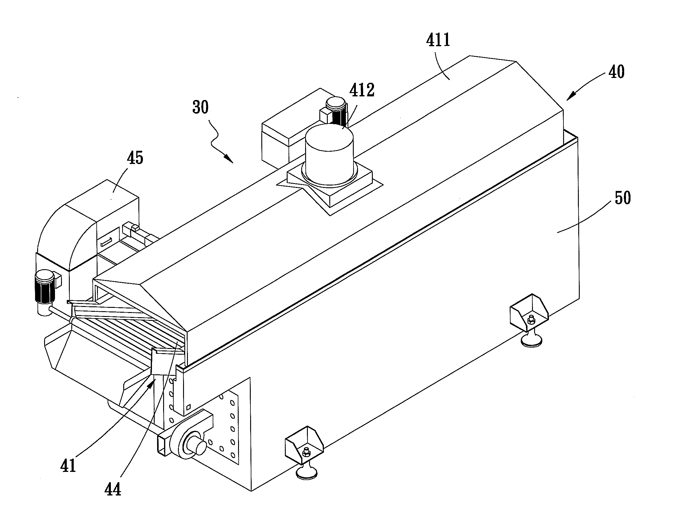
[0023]With reference to FIGS. 3 and 4, 5 for a conveying frying machine 30 in accordance with a preferred embodiment of the present invention, the conveying frying machine 30 comprises a conveying and frying device 40 having a shallow oil tank 41 that contains oil, a heat exchange device 50 installed under the shallow oil tank 41 for heating the conveying and frying device 40. An exhaust chamber 54 is formed between the conveying and frying device 40 and the heat exchange device 50. The exhaust chamber 54 is passed through the bottom of the shallow oil tank 41 of the conveying and frying device 40 for performing a secondary heating of the shallow oil tank 41.

[0024]The conveying and frying device 40 includes a shallow oil tank 41, an oil filter 45 disposed on an external side for filtering the oil, and a


PUM


Abstract

A conveying flying machine includes a conveying and frying device and a heat exchange device installed at a lower end thereof. An exhaust chamber is formed between the conveying and frying device and the heat exchange device. The exhaust chamber passes through the bottom of a shallow oil tank of the conveying and frying device to save the disposing space, and a burner installed on a side of the heat exchange device for heating the exhaust of combustion in the heating chamber. The exhaust is passed through a first exhaust end of the exhaust chamber and then discharged from a second exhaust end of the exhaust chamber for performing a secondary heating of the oil inside the shallow oil tank, so as to stabilize the quality of the deep fried food, ensure the heating of the shallow oil tank, and save energy.

Description


Claims


Application Information

Patent Timeline
Owner CHUAN YANG FOODS MACHINE
Why Eureka
Try Eureka