Electric energy meter turnover box clamping mechanism

A technology of clamping mechanism and turnover box, which is applied in the direction of measuring electrical variables, measuring devices, instruments, etc., can solve the problems of low work efficiency, time-consuming, large labor force, etc., so as to improve work efficiency, avoid manual operation, and reduce labor. The effect of labor

Active Publication Date: 2012-09-12
CHONGQING ELECTRIC POWER RES INST +2
View PDF8 Cites 4 Cited by
  • Summary
  • Abstract
  • Description
  • Claims
  • Application Information

AI Technical Summary

Problems solved by technology

The process of taking the discharge energy meter turnover box is manually operated, the operation method is single and time-consuming, the

Method used


Image

  • Electric energy meter turnover box clamping mechanism
  • Electric energy meter turnover box clamping mechanism
  • Electric energy meter turnover box clamping mechanism

Examples


Example Embodiment

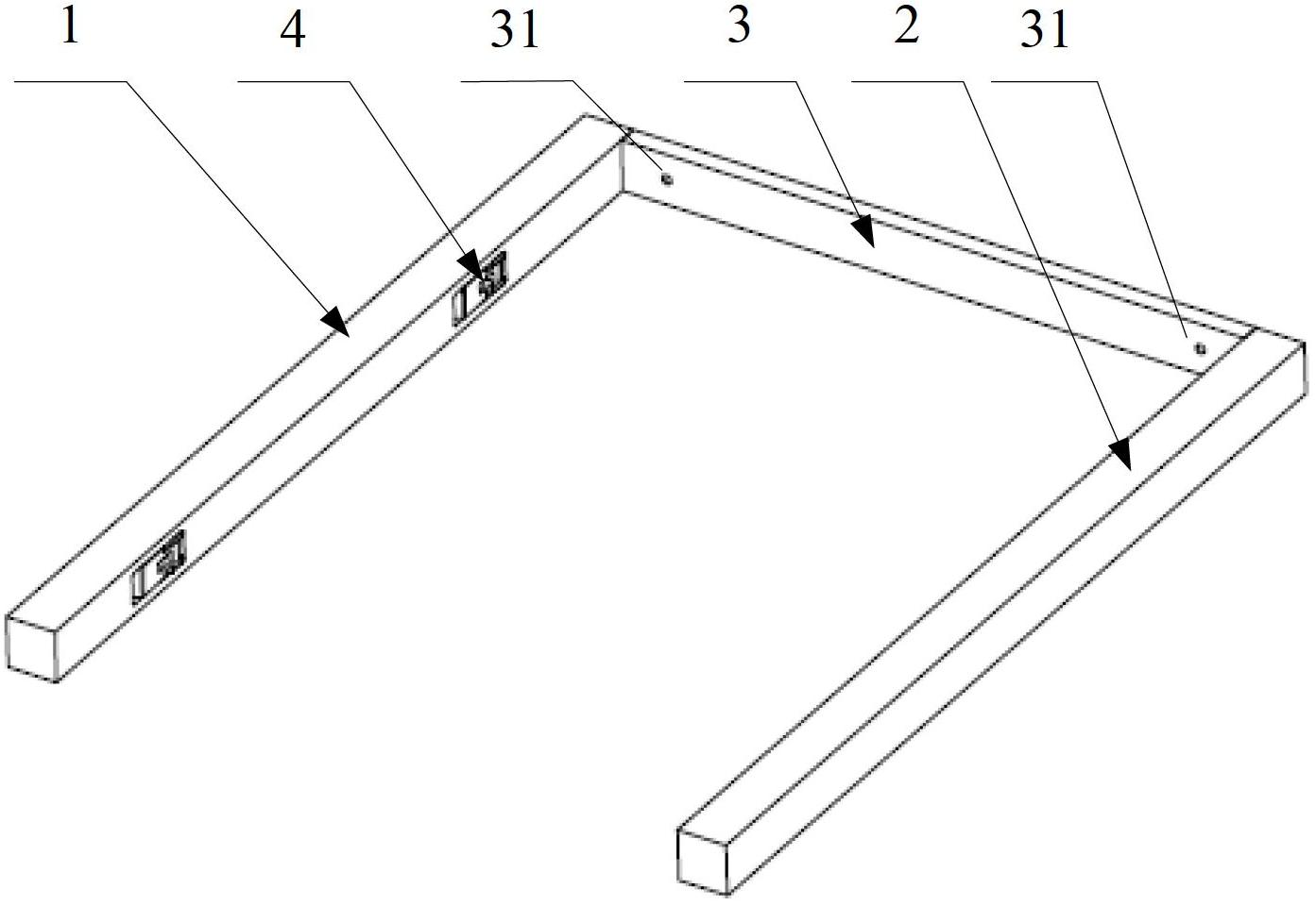
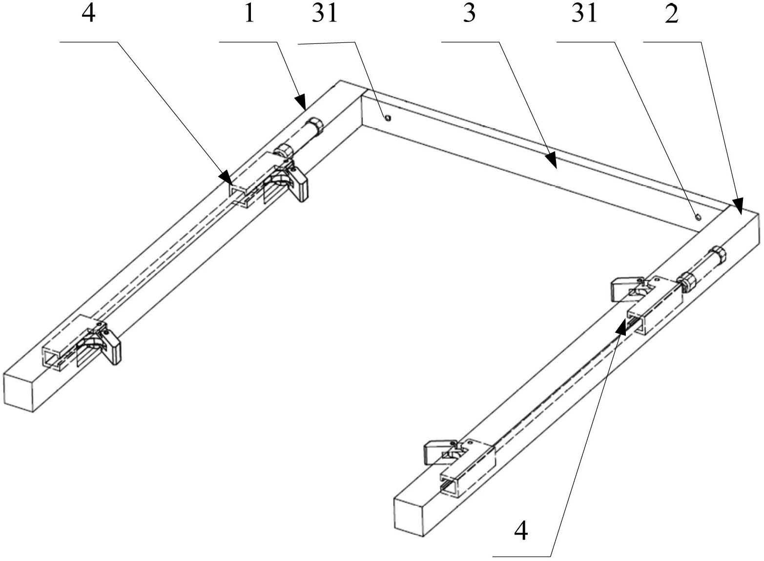
[0031] The invention discloses an electric energy meter turnover box clamping mechanism of an electric energy meter detection device, so as to reduce manual labor in the process of taking and placing the electric energy meter turnover box, thereby improving work efficiency.

[0032] The technical solutions in the embodiments of the present invention will be clearly and completely described below in conjunction with the accompanying drawings in the embodiments of the present invention. Obviously, the described embodiments are only a part of the embodiments of the present invention, rather than all the embodiments. Based on the embodiments of the present invention, all other embodiments obtained by those of ordinary skill in the art without creative work shall fall within the protection scope of the present invention.

[0033] Please refer to figure 1 with figure 2 , figure 1 It is a schematic diagram of the contraction of the clamping mechanism of the electric energy meter turnover box


PUM


Abstract

The invention discloses an electric energy meter turnover box clamping mechanism which comprises a first arm, a second arm, and an arm tail rod which is connected with the ends on the same sides of the first arm and the second arm, wherein at least one clamping device for clamping an electric energy meter turnover box is arranged in the first arm and the second arm. By utilizing the electric energy meter turnover box clamping mechanism, due to the arrangement of the first arm, the second arm, and the arm tail rod which is connected with the ends on the same sides of the first arm and the second arm, a space for accommodating the turnover box is defined, and due to the clamping actions of the clamping devices, the turnover box is clamped by the electric energy meter turnover box clamping mechanism, and the operation of clamping the turnover box is finished; and when the turnover box is required to be arranged, due to the retracting actions of the clamping devices, the turnover box is relatively separated from the electric energy meter turnover box clamping mechanism, and the operation of arranging the turnover box is finished. By utilizing the electric energy meter turnover box clamping mechanism, the functions of clamping and arranging the electric energy meter turnover box are realized, manual operation is avoided, the manual labor is greatly reduced, and the working efficiency is improved.

Description


Claims


Application Information

Patent Timeline
Owner CHONGQING ELECTRIC POWER RES INST
Why Eureka
Try Eureka