Chemical waste gas treatment and discharge device
A technology of waste gas treatment and discharge device, applied in transportation and packaging, chemical instruments and methods, dispersed particle filtration, etc., can solve the problems of reduced work efficiency, difficult operation, reduced economic benefits, etc., to improve adsorption efficiency, save labor The effect of labor and resource saving
- Summary
- Abstract
- Description
- Claims
- Application Information
AI Technical Summary
Problems solved by technology
Method used
Image

Examples
Example Embodiment
[0027] Example 1
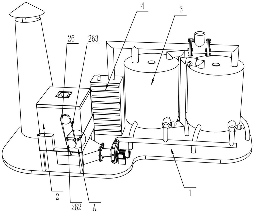
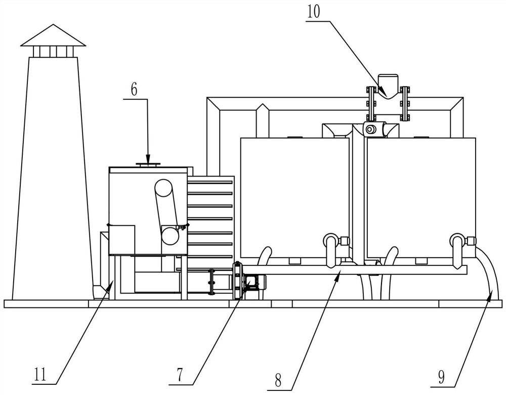
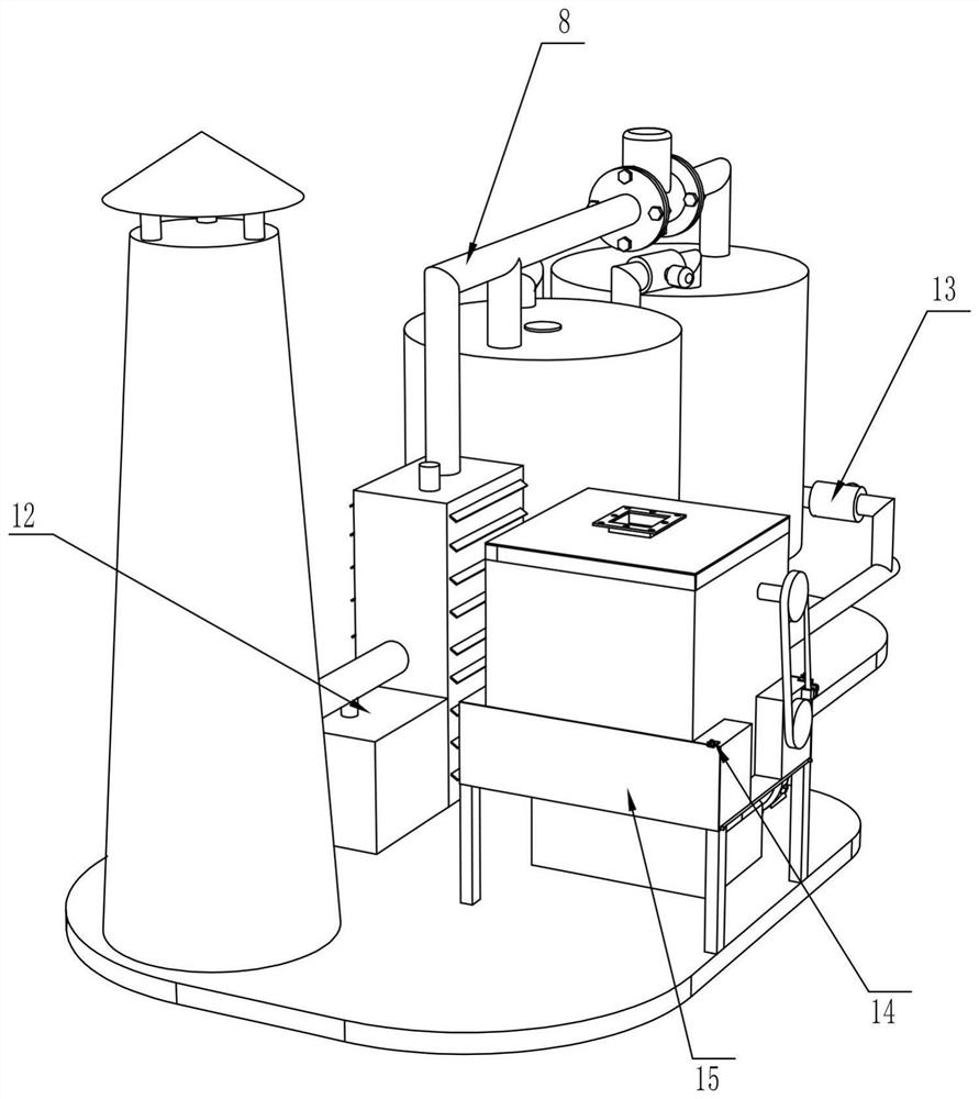
[0028] Such as Figure 1-Figure 7 As shown, a chemical exhaust gas treatment and emission device includes a bottom plate 1, a filter box 2, an adsorption box 3, a heating ring 301, a cooling box 4, a chimney 5, an air inlet 6, an induced draft fan 7, an air pipe 8, a first Supporting foot 9, one-way valve 10, second supporting foot 11, collecting tank 12, solenoid valve 13, lock 14, maintenance door 15, liquid level gauge 16 and heat sink 17, the top right side of bottom plate 1 is welded with multiple A support leg 9, two adsorption boxes 3 are welded on the top of the first support leg 9, a heating ring 301 is arranged inside the adsorption box 3, and a plurality of second support legs 11 are welded on the top left side of the bottom plate 1. The second support The top of the foot 11 is welded with a filter box 2, and the right side of the filter box 2 is provided with a maintenance door 15, the upper front side of the maintenance door 15 is provided with a lock
Example Embodiment
[0030] Example 2
[0031] On the basis of Example 1, such as Figure 1-Figure 7 As shown, it also includes a first rotating shaft 18, a concave plate 19, a fixed plate 20, a fixed frame 21, a carbon bed 22 and a stirring tooth 23. The bottom inner wall of the adsorption box 3 is rotatably connected with a first rotating shaft 18, A plurality of connecting rods are welded on the outer surface. The front end of the connecting rod away from the first rotating shaft 18 is welded with a concave plate 19. The circumferential inner wall of the suction box 3 is welded with a plurality of fixing plates 20, and the top of the fixing plate 20 is provided with two fixing frames 21 , The top of the fixing frame 21 is fixedly connected with a carbon bed 22, and the carbon bed 22 is sleeved with the first rotating shaft 18, the outer surface of the first rotating shaft 18 is welded with two arc-shaped plates, and the bottom of the arc-shaped plate is fixed with bolts The stirring teeth 23 are in c
Example Embodiment
[0033] Example 3
[0034] On the basis of Example 2, such as Figure 1-Figure 8 As shown, it also includes a second rotating shaft 24, a wind plate 25, a first pulley 26, a connecting shaft 261, a second pulley 262, a belt 263, a first gear 27, a second gear 28, a sliding groove plate 29, a splint 30 and the winding roller 31. The upper rear side of the filter box 2 is fitted with a second rotating shaft 24 through a bearing. The outer surface of the second rotating shaft 24 is connected with a plurality of wind plates 25, and the left end of the second rotating shaft 24 is connected with a key The first belt wheel 26, the upper front side of the filter box 2 is provided with a plug hole, a connecting shaft 261 is inserted into the plug hole, the right end of the connecting shaft 261 is connected with the first gear 27, and the right end of the connecting shaft 261 is connected with a key There is a second pulley 262, a belt 263 is wound on the first pulley 26 and the second pulley
PUM
 Abstract
Description
Claims
Application Information
 - R&D Engineer
- R&D Manager
- IP Professional
- Industry Leading Data Capabilities
- Powerful AI technology
- Patent DNA Extraction
Browse by: Latest US Patents, China's latest patents, Technical Efficacy Thesaurus, Application Domain, Technology Topic.
© 2024 PatSnap. All rights reserved.Legal|Privacy policy|Modern Slavery Act Transparency Statement|Sitemap