Map, positioning device, positioning system and positioning method thereof

A positioning system and positioning device technology, applied in the directions of maps/plans/charts, electromagnetic radiation induction, instruments, etc., can solve the problem of time-consuming searching for users, and achieve the effect of solving power consumption, saving power and improving accuracy.

Inactive Publication Date: 2012-09-26
KUNDA COMP TECHKUSN +1
View PDF3 Cites 9 Cited by
  • Summary
  • Abstract
  • Description
  • Claims
  • Application Information

AI Technical Summary

Benefits of technology

This patented technology allows users to easily find their location by showing them an icon that shows where they are located at different times during navigation. It also uses a special type of display called a corrector to make sure these icons stay accurate over longer periods of time without being affected negatively from any external factors like sunlight or rainwater. Overall this makes finding your own place quickly easier than traditional methods such as looking up maps manually.

Problems solved by technology

The technical problem addressed in this patented text relates how to create an efficient way to store large amounts of digital content (such as documents) onto electronic devices like smartphones without being too complicated or expensive due to their small storage capacities. This would make them more accessible to readers who may have difficulty remembering where each piece has been recorded correctly.

Method used


Image

  • Map, positioning device, positioning system and positioning method thereof
  • Map, positioning device, positioning system and positioning method thereof
  • Map, positioning device, positioning system and positioning method thereof

Examples


Embodiment Construction

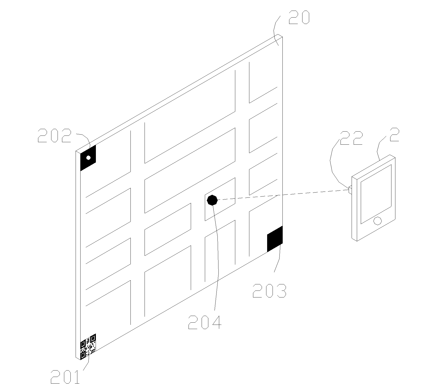
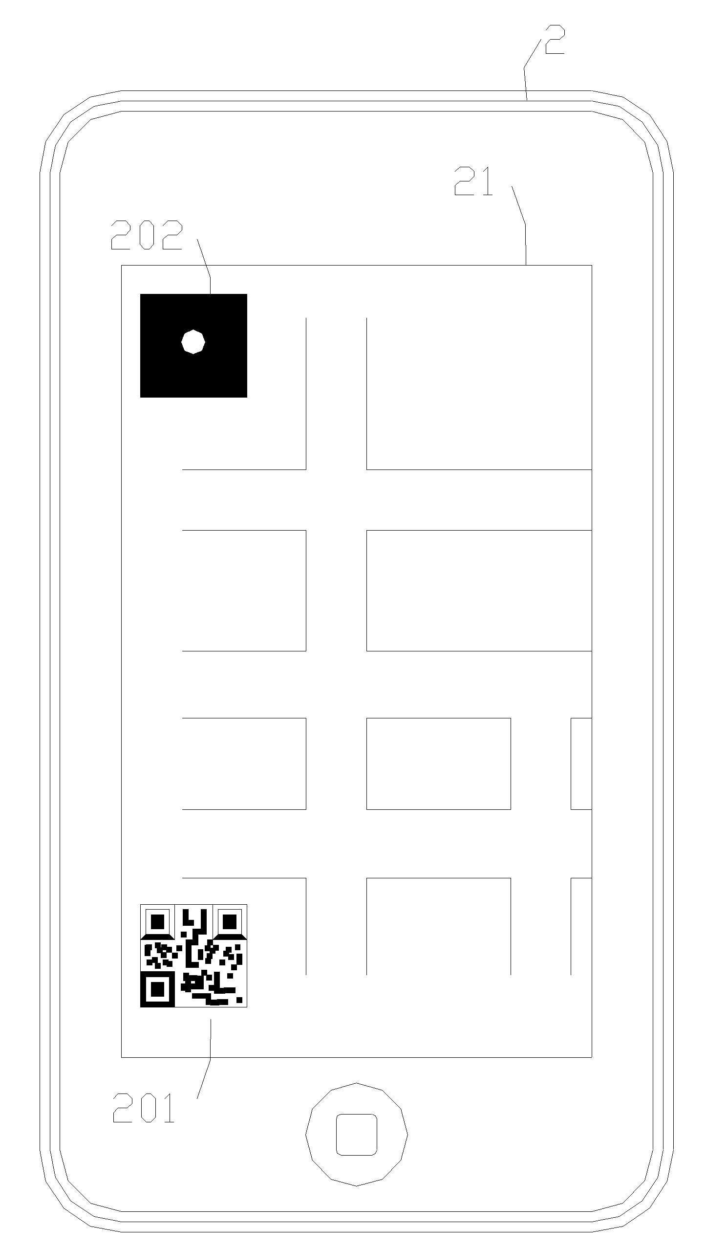
[0030] see figure 1 , which is a block diagram of the positioning system of the present invention. In the figure, the positioning system 1 includes a map 10 and a positioning device 11 . The positioning device 11 is electrically connected to an image capture unit 110, a satellite positioning unit 111, and a projection unit 113 with a control unit 112, wherein the control unit 112 further includes an identification module 1121 and a decoding module 1122; Each non-overlapping two-dimensional barcode 101 and several positioning points 102, the two-dimensional barcode 101 records the map information of the map 10, wherein the map information includes an image size, the information of each positioning point 102, and the position of each point on the map 10 A longitude value, a latitude value and the range of the longitude / latitude value included in the map 10 , wherein the information of each positioning point 102 includes a longitude value and a latitude value. When the user want


PUM


Abstract

The invention discloses a map, a positioning device, a positioning system and a positioning method thereof. The positioning method is suitable for a positioning system that includes a map and a positioning device. The positioning method comprises the following steps that: an image capture unit captures a map image according to the map; a satellite positioning unit provides position information according to the position of the positioning device; a control unit is utilized to receive and decode a two-dimensional bar code so as to obtain map information; when the control unit determines the position information is in the map image, a projection signal is generated and then is transmitted to an projection unit; and thus, the projection unit generates a projection spot based on the projection signal and is marked on the map.

Description


Claims


Application Information

Patent Timeline
Owner KUNDA COMP TECHKUSN
Why Eureka
Try Eureka