Mixing pile blade

A technology of stirring blades and stirring piles, which is applied to sheet pile walls, buildings, infrastructure projects, etc., can solve the problems of difficulty in construction of stirring piles and affect construction quality, and achieve the effect of simple structure and obvious effect.

Inactive Publication Date: 2012-10-03
宫能和
View PDF5 Cites 1 Cited by
  • Summary
  • Abstract
  • Description
  • Claims
  • Application Information

AI Technical Summary

Problems solved by technology

[0002] Before the present invention, in order to quickly discharge the water in the land reclamation project, many plastic drainage boards were vertically driven downwards, and the plastic drainage boards were buried in the foundation all the time, and then st

Method used


Image

  • Mixing pile blade
  • Mixing pile blade

Examples


Embodiment Construction

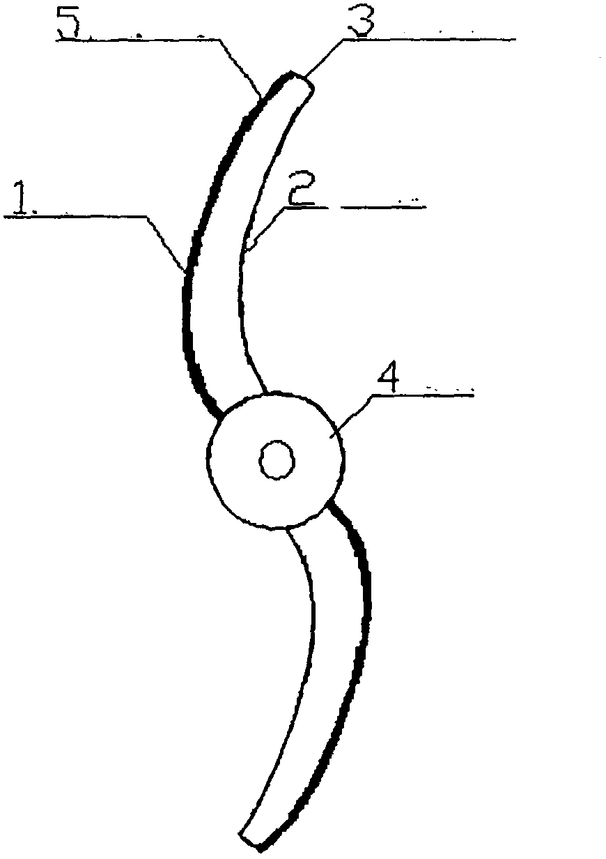
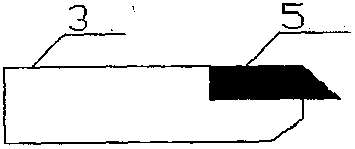
[0012] Such as figure 1 , figure 2 Shown:

[0013] The stirring blade 3 is connected to the drill pipe 4 (drive shaft), and the driving device (omitted, not shown) is connected to the drill pipe 4. The outside of the stirring blade 3 is arc-shaped to form an outer arc surface 1, and the inside is also arc-shaped to form an inner arc surface 2. , the arc of the outer arc surface 1 and the inner arc surface 2 can be the same or can be similar, and the rotation direction of the drill rod 4 is from the inner arc surface 2 to the outer arc surface 1, that is, the outside of the stirring blade 3 (the outer arc surface 1) is the stirring When the blade 3 rotates, it first encounters one side of the soil layer; on the outer arc surface 1 of the stirring blade 3, the cemented carbide 5 is inlaid and welded. The arc shapes on the outside and inside of the stirring blade 3 are set according to technical common sense.

[0014] Description of the application process of the present inventi


PUM


Abstract

The invention relates to a mixing pile blade, which adopts the structure that a driving device is connected with a drill rod, and the drill rod is fixedly connected with a mixing blade. The main technical characteristics are that the outer side of the mixing blade is an arc, namely, an outer cambered surface; the outer side of the mixing blade adopts the structure that the mixing blade is firstly contacted with one side of a soil layer during the rotation; an alloy is arranged on the outer cambered surface; and the rotation direction of the mixing blade is from the inner cambered surface to the outer cambered surface. The mixing pile blade solves the defects that the construction of the mixing pile is difficult and the construction quality is seriously affected due to the fact that the mixing blades of the mixing pile are wound by abandoned drain boards during the piling; the arc outer cambered surface of the mixing blade propels forwards and pushes the drain boards away, and prevents the winding of the drain boards, thereby guaranteeing the smooth piling of the mixing pile; and the mixing pile blade has the advantages of simple structure, low cost and remarkable effect.

Description


Claims


Application Information

Patent Timeline
Owner 宫能和
Why Eureka
Try Eureka