Furniture sponge drilling machine

A drilling machine and sponge technology, applied in metal processing and other directions, can solve the problems of affecting the use effect, deformation, and unable to control the direction of shrinkage, etc., to achieve high work efficiency, good effect, and avoid deformation

Inactive Publication Date: 2012-10-17
李钊怀
View PDF9 Cites 10 Cited by
  • Summary
  • Abstract
  • Description
  • Claims
  • Application Information

AI Technical Summary

Problems solved by technology

Although this method can quickly drill holes and the sponge will not be torn apart by the cutting force of the drill bit, it cannot control the shrinkage direction inside the sponge after the sponge is vertically compressed. When the hole is drilled and the sponge returns to its original shape, the drilled hole The bit has been deformed, which affects its use effect

Method used


Image

  • Furniture sponge drilling machine
  • Furniture sponge drilling machine
  • Furniture sponge drilling machine

Examples


Example Embodiment

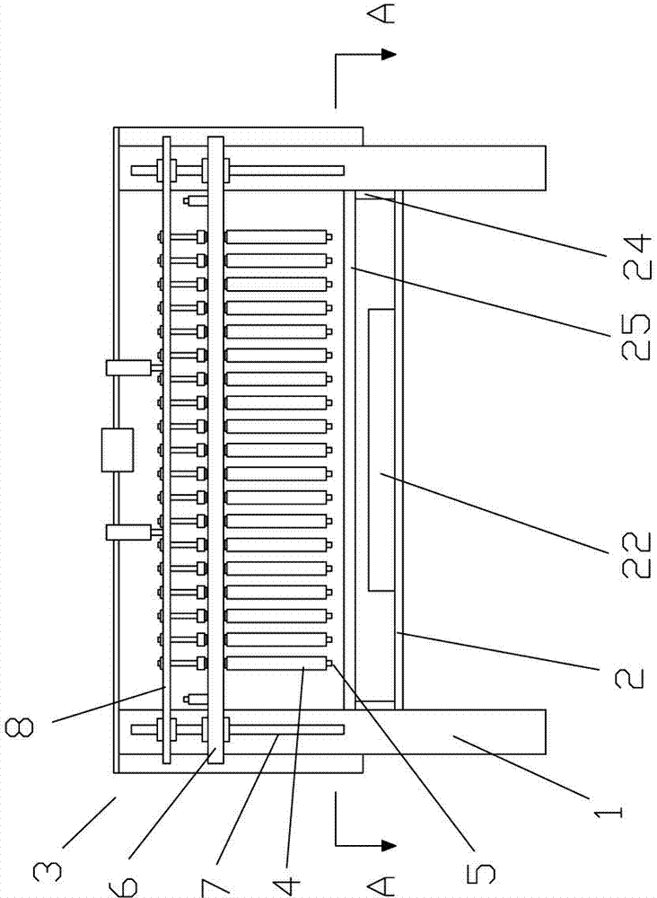
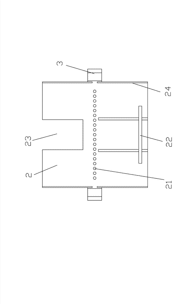
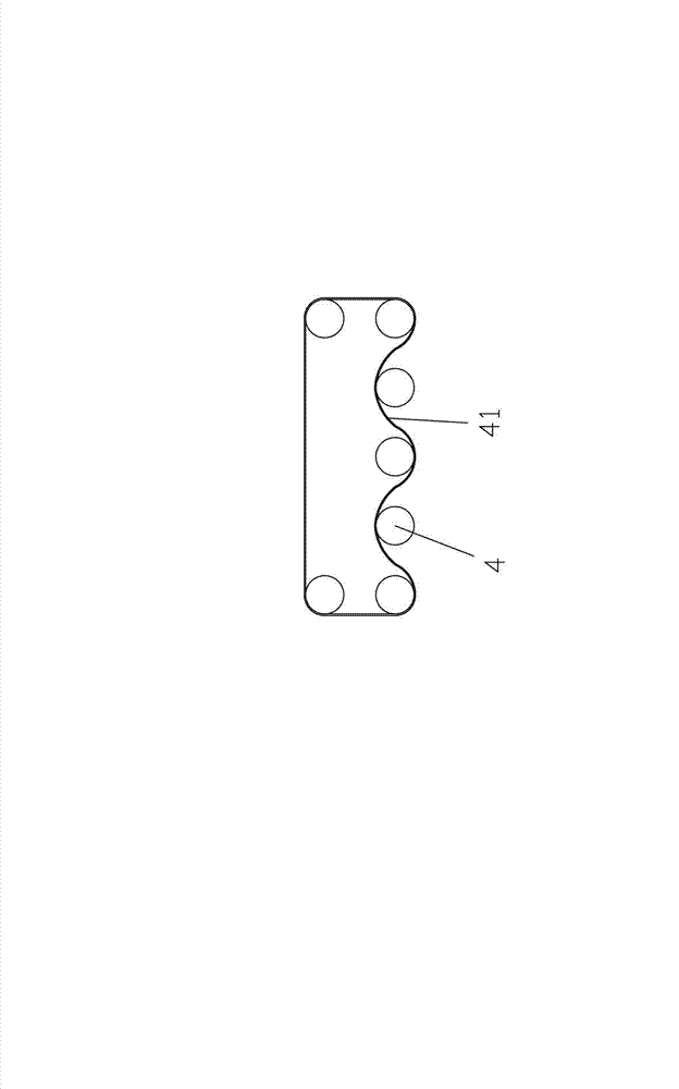
[0019] Reference figure 1 , figure 2 , image 3 , The present invention provides a furniture sponge drilling machine with good drilling effect, convenient use and high work efficiency, including a frame 1, on which a workbench 2 for placing furniture sponges is provided, and the workbench A gantry bracket 3 is provided in the middle of the gantry bracket 3. A number of hollow drill bits 4 that can move up and down are arranged horizontally on the gantry bracket 3. The rotation direction of the two adjacent hollow drill bits 4 is opposite, so that the adjacent two hollow drill bits are in contact with the furniture sponge The direction of force on the surface is opposite, and the force of the entire furniture sponge reaches a balanced state, which prevents the furniture sponge from deforming and ensures the drilling effect. Each hollow drill bit 4 is provided with a lifter 5 that can move up and down. When the hollow drill 4 is drilling, the lifter 5 moves up, and when the hollow


PUM


Abstract

The invention discloses a furniture sponge drilling machine which is good in drilling effect, convenient to use and high in working efficiency. The furniture sponge drilling machine comprises a rack, wherein the rack is provided with a workbench for placing furniture sponge, a gantry support is arranged in the middle of the workbench, a plurality of hollow drilling bits which can vertically move are horizontally arranged on the gantry support, the rotation directions of two adjacent hollow drilling bits are opposite, and a push rod which can vertically move is arranged in each hollow drilling bit. In the furniture sponge drilling machine, the plurality of hollow drilling bits which can vertically move are arranged above the workbench so as to drill a plurality of holes on the furniture sponge once, so that the working efficiency is high; and the rotation directions of two adjacent hollow drilling bits are opposite, so that the stress directions of the contact surfaces between the two adjacent hollow drilling bits and the furniture sponge are opposite, and the stress of the whole furniture sponge is in a balanced state so as to avoid deformation of the furniture sponge and ensure the drilling effect.

Description


Claims


Application Information

Patent Timeline
Owner 李钊怀
Why Eureka
Try Eureka