Smart grid OPGW (optical power ground wire) realization device

A smart grid and electrical port technology, applied in the direction of selection devices, multiplexing system selection devices, electrical components, etc., can solve the problems that optical fiber networks cannot be serially relayed, and achieve the effect of network serial relay transmission

Inactive Publication Date: 2012-12-12
苏州金纳信息技术有限公司
View PDF3 Cites 3 Cited by
  • Summary
  • Abstract
  • Description
  • Claims
  • Application Information

AI Technical Summary

Problems solved by technology

[0003] The problem to be solved: solve the problem that the

Method used


Image

  • Smart grid OPGW (optical power ground wire) realization device
  • Smart grid OPGW (optical power ground wire) realization device

Examples


example 1

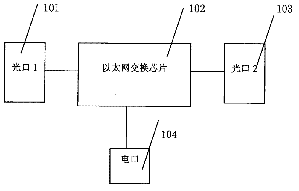
[0024] Preferred example 1: OPGW realizes reliable communication of optical fiber serial relay, and uses Ethernet switch chip to realize serial relay communication;

[0025] Such as figure 1 As shown, optical module 1 (101), Ethernet switching chip (102), optical module 2 (103), electrical port (104); optical module 1 (101) connects the optical interface 1 of Ethernet switching chip (102); The optical module 2 (103) is connected to the optical interface 2 of the Ethernet switching chip (102); the electrical port (104) is connected to the electrical interface of the Ethernet switching chip (102);

[0026] Ethernet switch chip (102) can adopt: the switch chip of Broadcom company or MARVELL company or RELTEK company or IC+ company or MICREL;

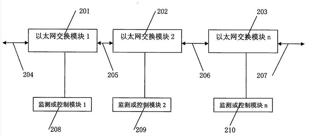
[0027] The Ethernet switching module is composed of four parts: optical module 1 (101), Ethernet switching chip (102), optical module 2 (103), and electrical port (104).

[0028] Such as figure 2 As shown, Ethernet switching module 1 (201)


PUM


Abstract

The invention relates to the smart grid communication by utilizing a switch chip to realize OPGW (optical power ground wire), in particular to a smart grid communication channel realization device of OPGW by utilizing an Ethernet switch chip to realize optical-fiber serial relay communication. The device comprises an optical module 1 (101), an Ethernet switch chip (102), an optical module 2 (103) and an electric port (104); the optical module 1 (101) is connected with an optical interface 1 of the Ethernet switch chip (102); the optical module 2 (103) is connected with an optical interface 2 of the Ethernet switch chip (102); the electric port (104) is connected with an electric interface of the Ethernet switch chip (102); the Ethernet switch chip (102) can adopts a switch chip manufactured by Broadcom company, MARVELL company, RELTEK company, IC+ company or the MICREL; and the optical module 1 (101), the Ethernet switch chip (102), the optical module 2 (103) and the electric port (104) forms an Ethernet switch module.

Description


Claims


Application Information

Patent Timeline
Owner 苏州金纳信息技术有限公司
Why Eureka
Try Eureka