Rear naked-eye three-dimensional (3D) display and display method

A naked-eye stereoscopic and display method technology, applied in stereoscopic systems, instruments, optics, etc., can solve the problems of inability to achieve high-resolution 2D/3D bidirectional conversion, large energy loss, and dark images, and achieve high-resolution 2D images. the effect of playback

Active Publication Date: 2013-01-16
GUANGZHOU MIDSTERO TECH CO LTD
View PDF3 Cites 15 Cited by
  • Summary
  • Abstract
  • Description
  • Claims
  • Application Information

AI Technical Summary

Benefits of technology

This patented technology allows for 3D imagery that shows different perspectives from what it's supposed to look like when looking through your eyewear or other device screen instead of just showing them sideways over each frame. It also enables synchronized playing of two dimensional videos while maintaining their original depth perception. Overall, this technology improves how we experience immersive virtual reality experiences such as gaming worldwide.

Problems solved by technology

This patented describes an improved way to create 3D displays called binocular or autosteroscopies. These techniques involve displaying multiple perspective views simultaneously onto one another instead of having each eye see only its own unique perspective. By placing these perspectives behind regular gratings placed between them, they become more visible than if all were worn separately due to their limited depth perception capabilities. Additionally, this technique allows users to switch back and forth within certain areas depending upon how far away they look down towards rather than just around usable space. Overall, this new approach improves visual quality and reduces power consumption over traditional methods like monitors.

Method used


Image

  • Rear naked-eye three-dimensional (3D) display and display method
  • Rear naked-eye three-dimensional (3D) display and display method
  • Rear naked-eye three-dimensional (3D) display and display method

Examples


Embodiment 1

[0026] Structure of a stereoscopic display

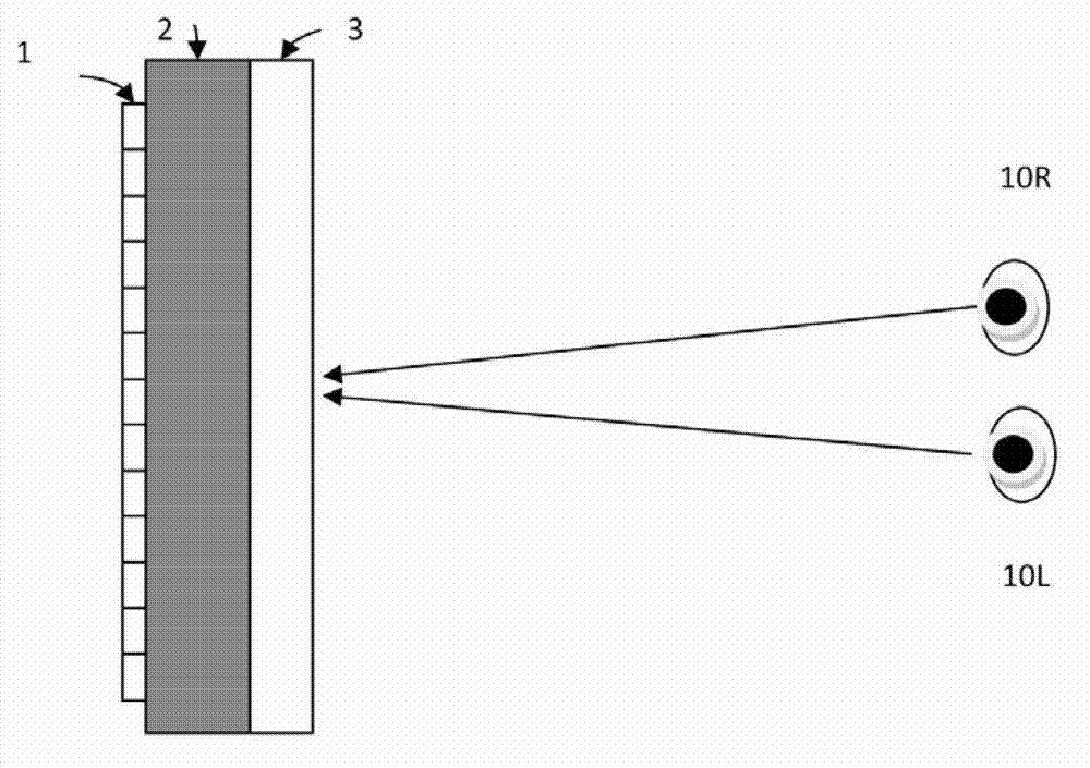
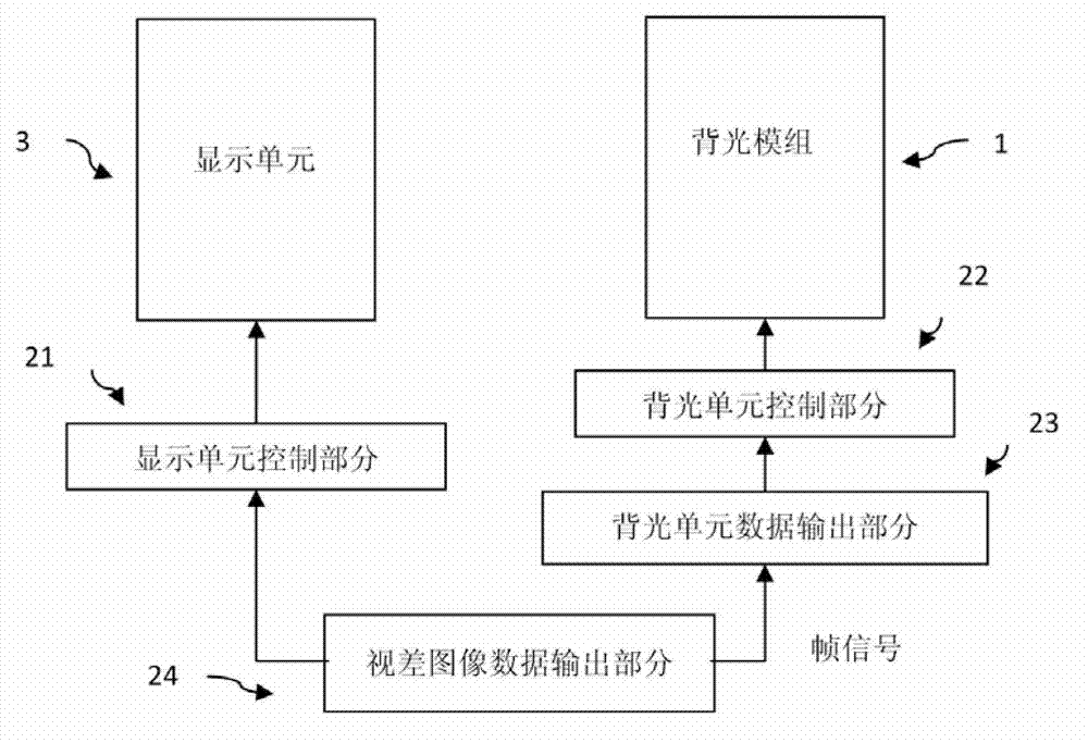
[0027] figure 1 An overall structural diagram of the naked-eye stereoscopic display without resolution reduction of the embodiment is shown. figure 2 A block diagram of a circuit responsible for display control in the naked-eye stereoscopic display is shown. Such as figure 1 As shown, the naked-eye three-dimensional display includes: an image display unit 3 (which can be a liquid crystal display (LCD) panel, an organic light-emitting display (OLED) panel, a transparent organic light-emitting display (TOLED) panel, preferably a liquid crystal display panel), arranged on the image The optical element 2 on the back of the display unit 3 (can be a lens, a Fresnel lens, a linear Fresnel lens and their array, a cylindrical lens array, and the above-mentioned devices and arrays composed of liquid crystal or other materials with similar functions ), and the backlight module 1 arranged behind the optical element 2 . The backlight module

Embodiment 2

[0050] Next, the present invention will describe the naked-eye stereoscopic display of Embodiment 2. The same reference numerals are used for the same components in the autostereoscopic display according to Embodiment 1, and will not be described again.

[0051] In the above-mentioned embodiment 1, a binocular stereoscopic display is described as an example, but this embodiment 2 is applicable to the case of multi-view stereoscopic display. In the case of stereoscopic display with m viewing angles, the backlight part is subdivided into 2m small units, m small units are used as light sources for the left eye point of view, and m small units are used as light sources for the right eye point of view. Such as Figure 5B As shown, what is displayed is not only a three-dimensional display with three viewing angles, each backlight group in the backlight part is as follows Figure 5B As shown, it is subdivided into six small units, three small units are used as light sources for the le


PUM


Abstract

The invention discloses a rear naked-eye three-dimensional (3D) display and a display method. The rear naked-eye 3D display comprises an image display unit, an optical element and a backlight module, wherein the image display unit can provide a display panel of a fully-high-resolution parallax image; the optical element propagates backlight energy to different visual areas in space; and the backlight module is formed by combining a switch and small backlight units, and the brightness of each small backlight unit can be freely controlled. Light which is emitted by the backlight module passes through the optical element, penetrates through the image display unit and then is used for loading the parallax image, so different parallax images can be seen through eyes at different spatial positions, or different images can be seen at different viewpoints. Meanwhile, by controlling the specific brightness combination of the small backlight units in the backlight module, a high-resolution two-dimensional (2D) image can be played. By the invention, under the condition that 3D display is realized, adding of glasses is eliminated, the resolution of the display is prevented from being reduced, and 2D/3D bidirectional switching without resolution reduction is realized.

Description


Claims


Application Information

Patent Timeline
Owner GUANGZHOU MIDSTERO TECH CO LTD
Why Eureka
Try Eureka