Circuit for realizing constant current control in primary control switch power converter

A switching power supply and primary side control technology, which is applied in the direction of converting DC power input to DC power output, converting AC power input to DC power output, and adjusting electrical variables, etc., can solve problems such as ineffective constant current control, and achieve Constant output current, suitable for a wide range of effects

Active Publication Date: 2013-03-20
WUXI SI POWER MICRO ELECTRONICS
View PDF4 Cites 5 Cited by
  • Summary
  • Abstract
  • Description
  • Claims
  • Application Information

AI Technical Summary

Benefits of technology

This technology allows for accurate measurement of changes made over time during operation without relying solely upon external factors like temperature or pressure. It uses an analog-to-digital converter (ADC) with multiple input terminals connected together through resistive elements called transistors. By sampling and holding this feedback voltage before converting back into its original form, the system measures how well the device works at different frequencies based on these measurements. Additionally, there are also sensed values from other components such as capacitors used in the oscillators' circuits. These data help adjust the duty cycle of each component to achieve consistency across all operating conditions. Overall, this technology helps improve safety and reliability while minimizing any potential issues related to environmental variables.

Problems solved by technology

This patented technical problem addressed in this patents relates to improving the performance and functionality of conventional electrical equipment (such as cameras) while reducing costs associated therewith without sacrificially increasing overall system sizes or requiring bulky external parts like regulators. Conventional methods involving multiple smaller components result in increased complexity and reduced security factors when incorporated into these systems. Therefore, an improved solution needs to be provided which allows for more efficient and reliable operation over longer periods of times.

Method used


Image

  • Circuit for realizing constant current control in primary control switch power converter
  • Circuit for realizing constant current control in primary control switch power converter
  • Circuit for realizing constant current control in primary control switch power converter

Examples


Embodiment Construction

[0034] The present invention will be further described below in conjunction with specific drawings and embodiments.

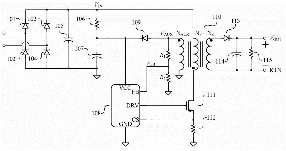
[0035] Such as figure 1 Shown: is the circuit schematic diagram of the existing primary side control switching power supply converter, which includes the first rectifier diode 101, the second rectifier diode 102, the third rectifier diode 103 and the fourth rectifier diode 104, the first rectifier diode 101 The cathode terminal is connected to the cathode terminal of the second rectifying diode 102, the anode terminal of the first rectifying diode 101 is connected to the cathode terminal of the third rectifying diode 103, and the anode terminal of the second rectifying diode 102 is connected to the cathode terminal of the fourth rectifying diode 104 The anode terminals of the third rectifier diode 103 and the fourth rectifier diode 104 are grounded to form a rectifier circuit for rectifying the input 110V or 220V AC. The cathode terminal of the first rectifier di


PUM


Abstract

The invention relates to a circuit for realizing constant current control in a primary control switch power converter. The circuit comprises a controller, wherein the controller comprises a sampling/holding circuit, a voltage/current conversion circuit, an oscillator circuit, a flip-flop and a current limiting comparator; the sampling/holding circuit samples and holds feedback voltage VFB and inputs the feedback voltage VFB to the voltage/current conversion circuit; the voltage/current conversion circuit converts the feedback voltage VFB to obtain required control current; the oscillator circuit outputs a corresponding oscillation frequency signal according to the control current, and inputs the oscillation frequency signal to a setting end of the flip-flop; when the oscillation frequency signal is at a high level, an output ends of the flip-flop outputs a high level signal to switch on a driving power tube; and when sampling voltage VCS is higher than reference voltage VREF of an antiphase end of the current limiting comparator, the current limiting comparator outputs a current limiting signal to allow the flip-flop to output a low level so as to switch off the power tube. The circuit is compact in structure, wide in application scope, safe and reliable, and can realize the constant current control.

Description


Claims


Application Information

Patent Timeline
Owner WUXI SI POWER MICRO ELECTRONICS
Why Eureka
Try Eureka