Tensioning and locking device for chain of chain saw

A technology of a chain tensioning device and a locking device is applied in the attachment devices of sawing machines, sawing machine devices, metal sawing equipment and other directions, which can solve the problems of inconvenient operation, complicated tensioning method and process, and achieve the effect of simple and convenient operation.

Inactive Publication Date: 2013-03-27
NANJING CHERVON IND
View PDF5 Cites 3 Cited by
  • Summary
  • Abstract
  • Description
  • Claims
  • Application Information

AI Technical Summary

Benefits of technology

This technology allows for easy movement when adjusting chains by pulling on an end or pushing it backward with one hand instead of two hands while keeping them still connected together through a mechanism called a linkage system.

Problems solved by technology

The technical problem addressed by this patented technology relates to maintaining proper chain tightness when changing from one type or brand to another without causing damage caused by too much pressure being applied over an extended area.

Method used


Image

  • Tensioning and locking device for chain of chain saw
  • Tensioning and locking device for chain of chain saw
  • Tensioning and locking device for chain of chain saw

Examples


Embodiment Construction

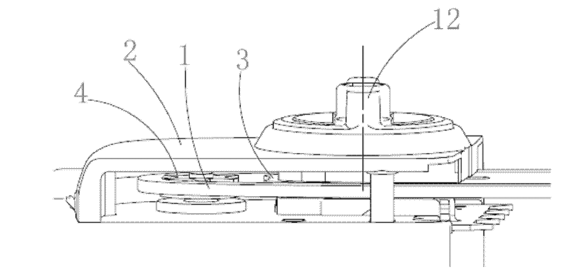
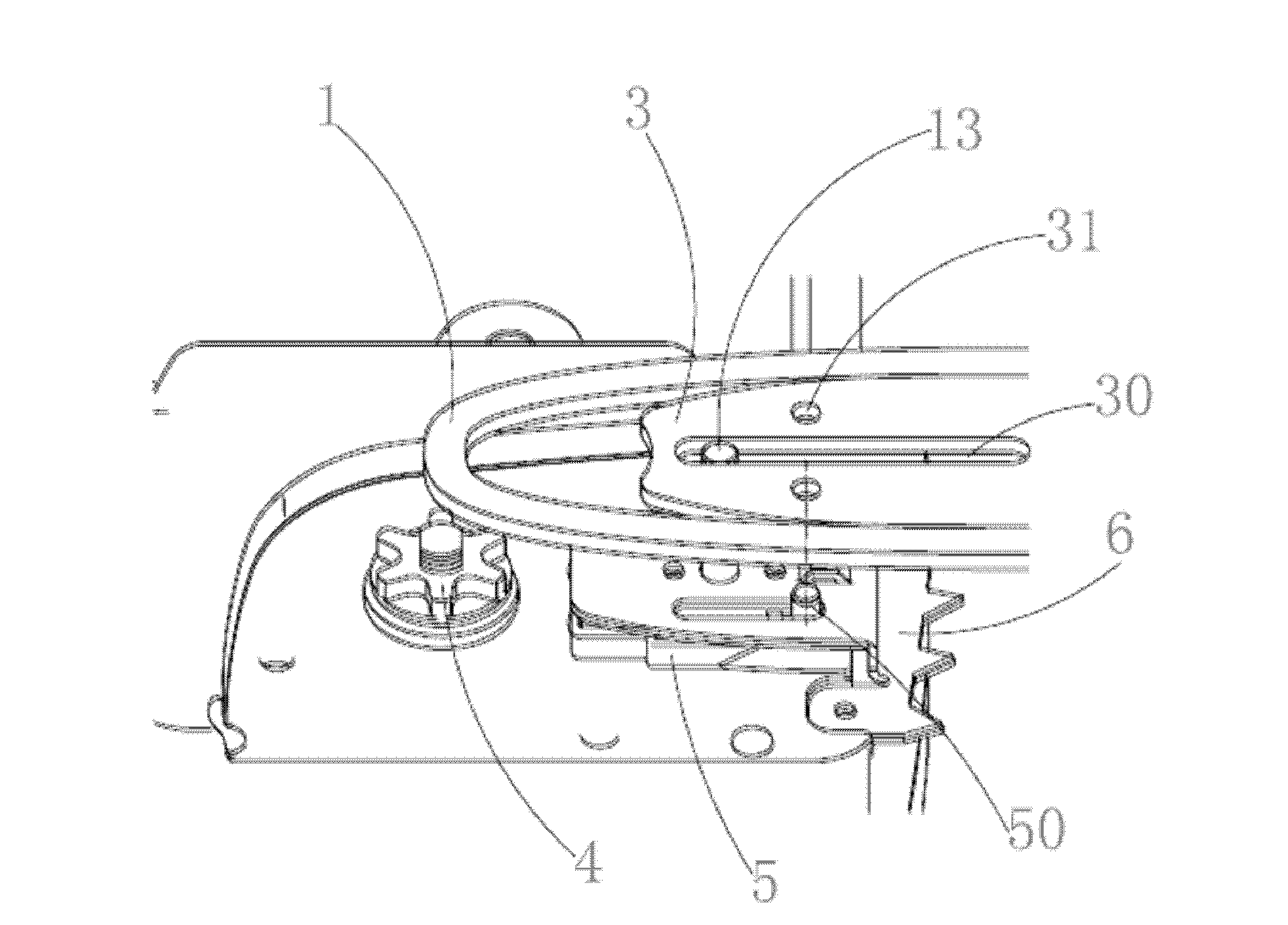
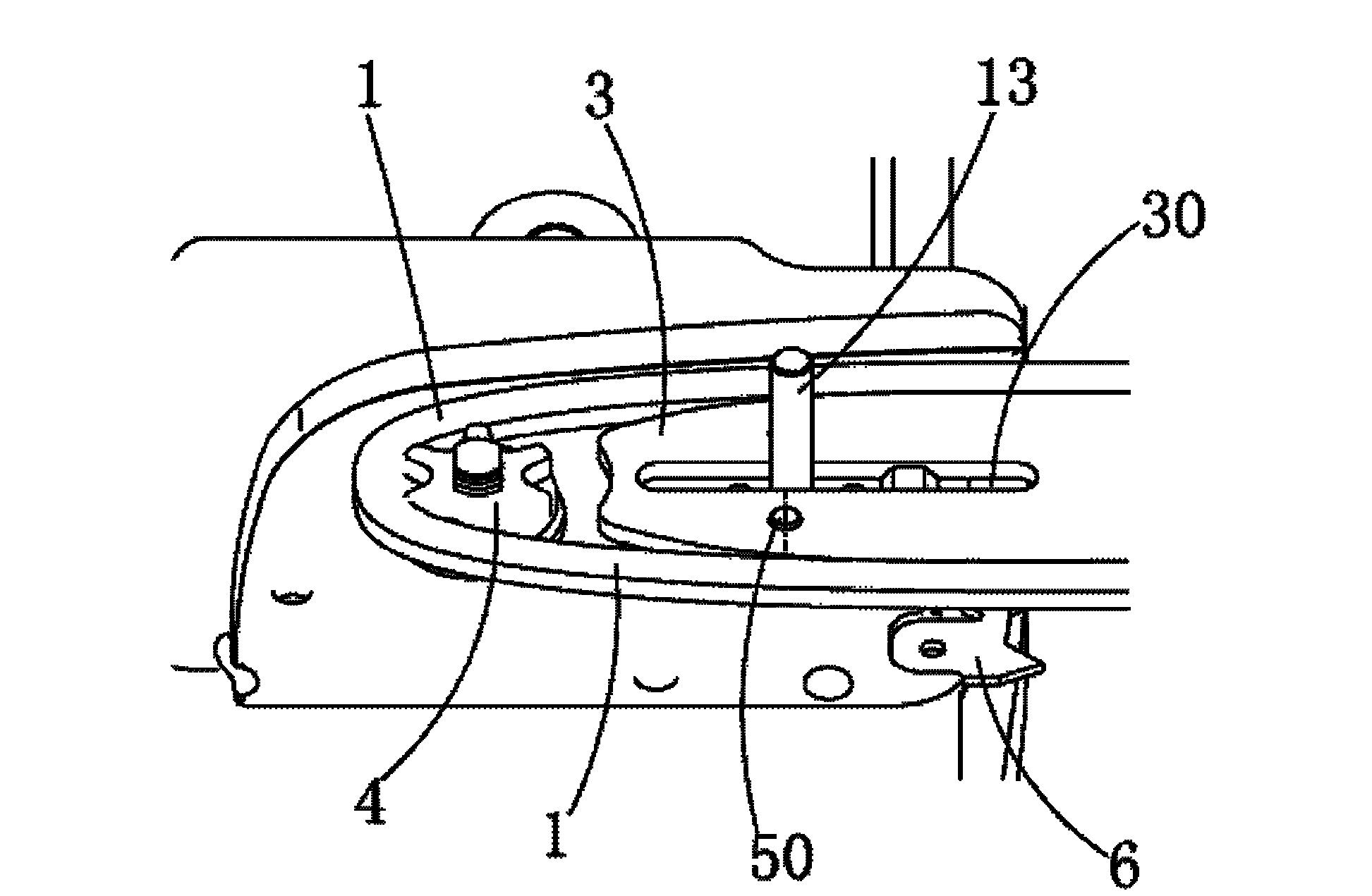
[0016] Please refer to Figure 1 to Figure 5 As shown, the chainsaw 100 according to the first embodiment of the present invention includes a chain 1, a chain tensioning device assembled with the chain 1 and a locking device for locking the chain tensioning device. In the chainsaw 100 according to the first embodiment of the present invention, The chain tensioning device includes a chain cover plate 2, a guide plate 3 installed with the chain, a sprocket 4 on which one end of the chain 1 is clamped, and a tension block installed with the guide plate 3 5 and a driving device that drives the tension block 5 towards the normal direction of the guide plate 3 plane and away from the sprocket 4 direction. In the first embodiment of the present invention, the extension direction of the plane of the guide plate 3 is defined as the X-axis direction, and the normal direction of the plane of the guide plate 3 is defined as the Y-axis direction. The guide plate 3 in the chain saw 100 of the


PUM


Abstract

The invention relates to a tensioning and locking device for a chain of a chain saw, which comprises the chain, a chain tensioning device mutually assembled with the chain, and a locking device for locking the chain tensioning device, wherein the chain tensioning device comprises a guide plate arranged together with the chain, a chain sprocket enabling one end of the chain to be clamped on the chain sprocket, a tensioning block arranged together with the guide plate, and a drive device for driving the tensioning block to move towards a normal direction of a plane of the guide plate and a direction deviate from the chain sprocket. In a tensioning process of the chain, the tensioning block is at a movement state, and the tensioning block is moved in the direction deviate from the chain sprocket so as to drive the guide plate to move along the same direction, so that the aim of tensioning the chain is achieved, and the operation is simple and convenient.

Description


Claims


Application Information

Patent Timeline
Owner NANJING CHERVON IND
Why Eureka
Try Eureka