Current source unit circuit of current-steering digital analog converter

A technology of digital-to-analog converters and unit circuits, which is applied in the direction of digital-to-analog converters, etc., can solve the problems of current-steering digital-to-analog converters such as the deterioration of dynamic performance, and achieve widespread use, improve glitches, and achieve simple effects

Inactive Publication Date: 2013-04-03
NORTH CHINA UNIVERSITY OF TECHNOLOGY
View PDF5 Cites 4 Cited by
  • Summary
  • Abstract
  • Description
  • Claims
  • Application Information

AI Technical Summary

Benefits of technology

This technology reduces changes caused by changing voltage levels for controlling signals through special connections between different components like MOS (metal oxide semiconductor) devices or other electronic elements that are involved with analog circuits. By reducing this variation, it becomes possible to improve the overall efficiency and accuracy of these systems while still maintaining their simplicity compared to traditional methods such as phase locked loops.

Problems solved by technology

This patented technical problem addressed in this patents relates to improving the quality (accuracy) and efficiency of current analog-converting circuits used in electronically driven display systems like liquid crystal displays or organic light emitting diodes (OLEDs). Current methods have limitations with respecting both resolution and response times required for accurate analog-signal conversion at these speeds. Therefore there needs better ways to improve the stability and effectiveness of current sources that can accurately represent complex waveforms without affecting their characteristics over large distances.

Method used


Image

  • Current source unit circuit of current-steering digital analog converter
  • Current source unit circuit of current-steering digital analog converter
  • Current source unit circuit of current-steering digital analog converter

Examples


Embodiment Construction

[0018] Below in conjunction with accompanying drawing and embodiment the present invention will be further described:

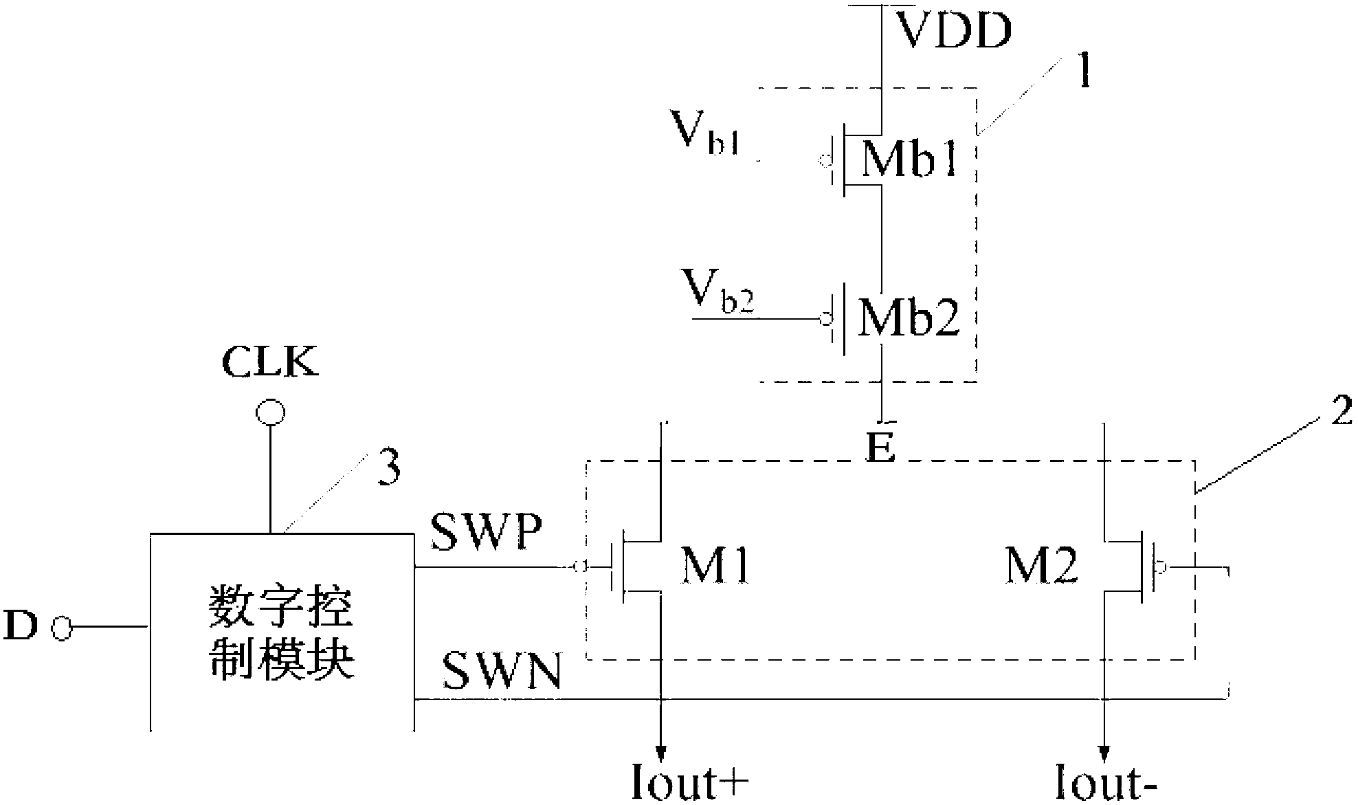
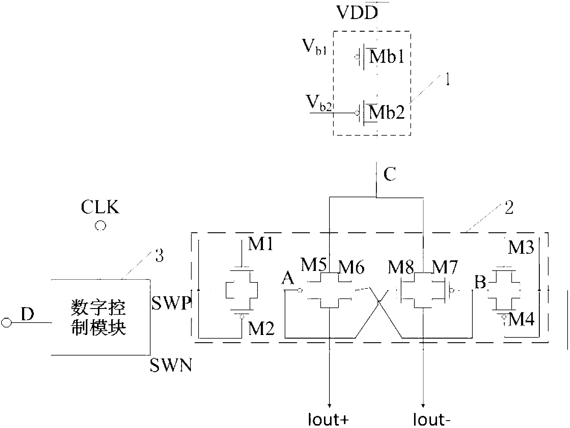
[0019] Such as image 3 As shown, the present invention includes the following three modules: a current source module, a switch module and a digital control module, specifically,

[0020] The current source module includes two upper and lower PMOS transistors Mb1 and Mb2, wherein the gates of Mb1 and Mb2 are respectively connected to external bias signals Vb1 and Vb2, the source of Mb1 is connected to an external voltage source VDD, the drain of Mb1 is connected to the voltage source of M2 The sources are connected together, and the drain of the Mb2 tube is connected to the common node C of the M5, M5, M7 and M8 tubes.

[0021] The input signal of the digital control module is the clock signal CLK, the input digital signal D, the output signal of the digital control module is a pair of inverted signals SWP and SWN, the high level of these two signals is close t


PUM


Abstract

The invention belongs to the field of integrated circuit design, and particularly relates to a current source unit circuit of a current-steering digital analog converter. The current source unit circuit comprises a current source module, a switch module and a digital control module, wherein the current source module comprises a current source tube Mb2 and a current source tube Mb1, the digital control module comprises a first signal output end SWP and a second signal output end SWN, and the signals output by the first signal output end SWP and the second signal output end SWN are contrary. The switch module is formed by a control signal processing module and a control switch module. Via four MOS (metal oxide semiconductor) tubes including M1, M2, M3 and M4 which are particularly connected, variation amplitude of a control signal is reduced by about two threshold voltage, glitch of an output signal of the current-steering digital analog converter is reduced, dynamic performance is improved, and the current source unit circuit can be widely applied on the current-steering digital analog converter. Meanwhile, the utilization of a complementation control switch can also improve the glitch.

Description


Claims


Application Information

Patent Timeline
Owner NORTH CHINA UNIVERSITY OF TECHNOLOGY
Why Eureka
Try Eureka