Oily sewage and sludge separation device

A separation device and water sludge technology, which is applied in the direction of water/sewage multi-stage treatment, water/sludge/sewage treatment, chemical instruments and methods, etc., can solve the problems of unsatisfactory treatment effect and complex equipment structure, and achieve structural Simple, high extraction rate and extraction efficiency, good water treatment effect

Inactive Publication Date: 2013-04-24
陕西华豫环境科技有限公司
View PDF8 Cites 4 Cited by
  • Summary
  • Abstract
  • Description
  • Claims
  • Application Information

AI Technical Summary

Benefits of technology

This new design for an oil sided wastewater system uses special materials that help separate soluble organic matter called greasy liquid residue or bacteria suspended therein. These particles stick together when they come off during processing causing them to be difficultly separated out even after being treated properly. By adding these special material beforehand, this technology allows more effective treatments while reducing environmental concerns associated with disposal processes such as incineration.

Problems solved by technology

This patented technical problem addressed in this patents relates to treating wastewater from various industrial processes that produce large amounts of water-based substances such as paper mill effluents or oil drilling operations during their manufacturing stages. These wastes are commonly referred to as black liquor (BL) which can harm both humans and wildlife by causing environmental concerns like contamination due to its high content of organic matter. Current methods involve complex procedures with poor results.

Method used


Image

  • Oily sewage and sludge separation device
  • Oily sewage and sludge separation device
  • Oily sewage and sludge separation device

Examples


Embodiment Construction

[0032] Embodiments of the present invention will be described below with reference to the drawings. Elements and features described in one drawing or one embodiment of the present invention may be combined with elements and features shown in one or more other drawings or embodiments. It should be noted that representation and description of components and processes that are not related to the present invention and known to those of ordinary skill in the art are omitted from the drawings and descriptions for the purpose of clarity.

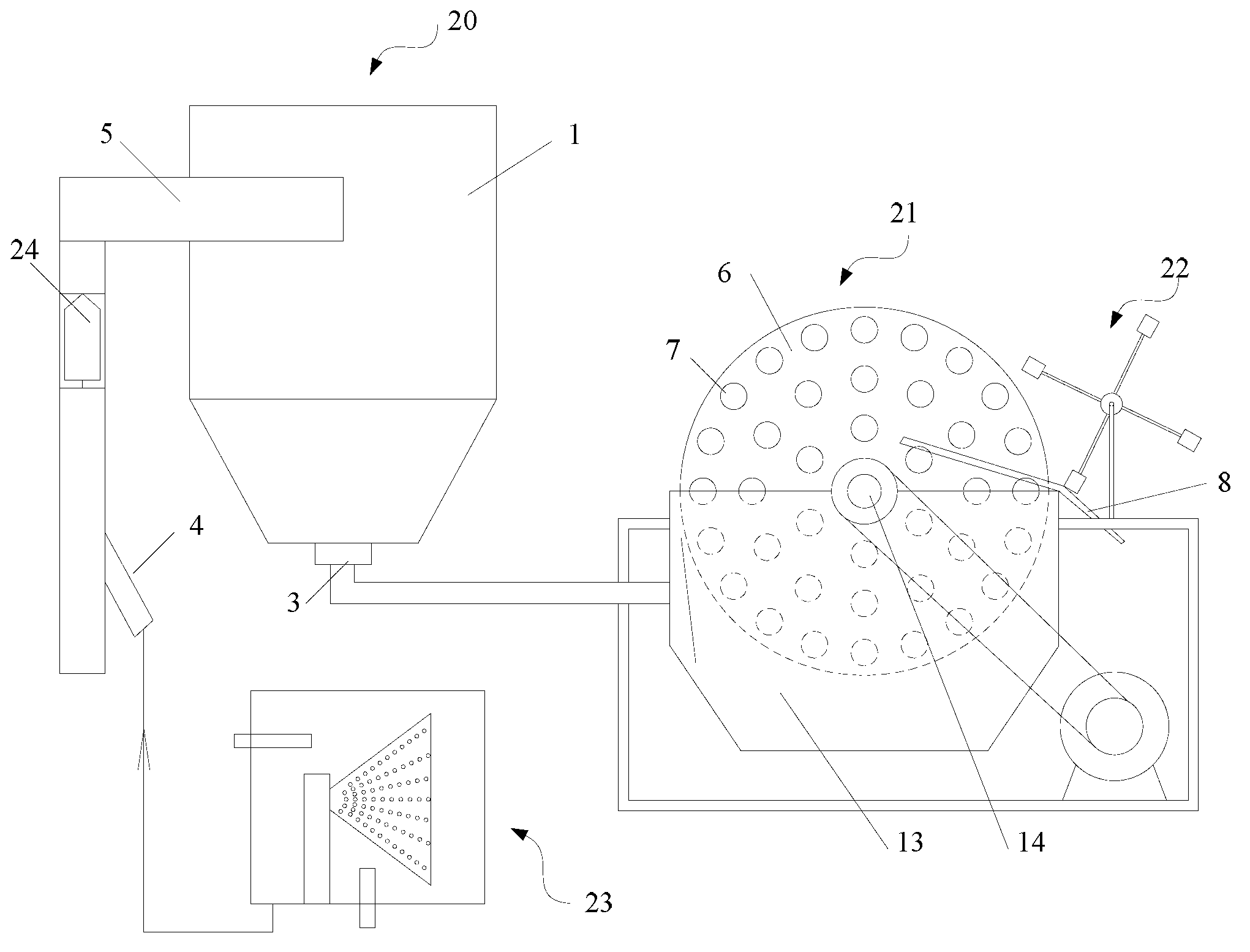
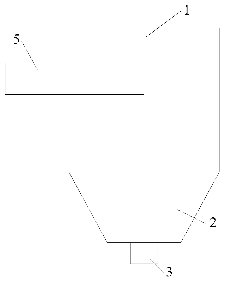
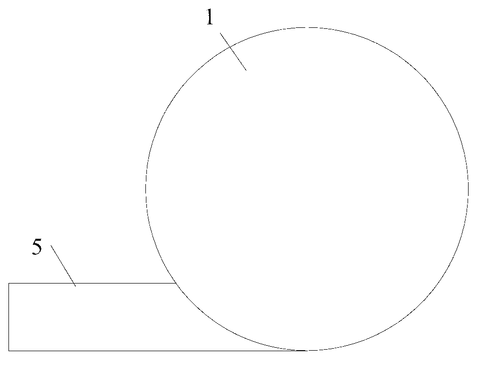
[0033] figure 1 Schematic diagram of the structure of the oily sewage sludge separation device provided by the embodiment of the present invention; as figure 1 As shown, the oily sewage sludge separation device provided in the embodiment of the present invention includes a reactor 20 and a magnetic mud-water separator 21 .

[0034] Wherein, the reactor 20 includes a reactor tank body 1 with a revolving body structure, the side wall of the reactor ta


PUM


Abstract

The invention provides an oily sewage and sludge separation device, which comprises a reactor and a magnetic muddy water separator, wherein the reactor comprises a reactor tank body with a revolved structure; a first liquid inlet pipe is arranged on the side wall of the reactor tank body; a first liquid outlet is formed on the bottom of the reactor tank body; the magnetic muddy water separator comprises a separator box body; a disk shaft is rotatably arranged in the separator box body; at least one disk is fixedly connected to the disk shaft; a magnetic body is arranged on the disk; mud scraping boards are evenly arranged on two sides of the disk and are contacted and matched up with the side wall of the disk; and the first liquid outlet is communicated with the separator box body. The scheme is simple in structure, the sludge and sewage are reacted with agents in the reactor, flocculent precipitate is formed and then is discharged in the separator box body, and the precipitate is adsorbed on the disk to be separated from water, so that the removal rate and the removal efficiency of the precipitate are high, good water treatment effect is achieved, discharged water can reach A1 standard of national regulation, and the solid content of the removed precipitate is not less than 35%.

Description


Claims


Application Information

Patent Timeline
Owner 陕西华豫环境科技有限公司
Why Eureka
Try Eureka