Compressive underground engineering pipe

An underground engineering and pipe body technology, applied in the field of engineering pipes, can solve the problems of no classification and storage function, unsatisfactory compression and impact resistance, poor corrosion resistance, etc., to achieve convenient classification and storage, novel structural design, and improved impact resistance The effect of capacity and pressure resistance

Inactive Publication Date: 2013-05-01
CHENGDU BINGUO TECH
View PDF7 Cites 4 Cited by
  • Summary
  • Abstract
  • Description
  • Claims
  • Application Information

AI Technical Summary

Problems solved by technology

[0002] In the prior art, the underground engineering pipe generally adopts a circular pipe structure, but the compressive and impact resistance of such a structure is not ideal enough to meet the

Method used


Image

  • Compressive underground engineering pipe

Examples


Example Embodiment

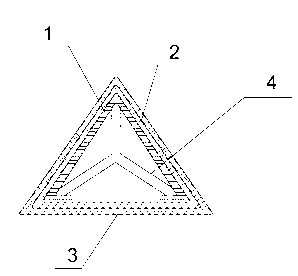
[0012] As an embodiment of the present invention, see figure 1 , The present invention includes a pipe body 1, the cross section of the pipe body 1 is an equilateral triangle, the outer wall of the pipe body 1 is provided with a reinforcing layer 2 and an anti-corrosion layer 3 sequentially from the inside to the outside. The tubes are glued together, and the tube body 1 is provided with a "herringbone" shaped partition 4, which divides the tube body 1 into three independent chambers. The top corner of the pipe body 1 is chamfered.

[0013] The section of the pipe body 1 is an equilateral triangle, which directly improves the overall resistance and pressure resistance. The reinforcement layer 2 can further improve the overall strength, and the anticorrosion layer 3 can improve the corrosion resistance. The pipe body 1 is provided with a partition 4, Convenient for classified storage.


PUM


Abstract

The invention discloses a compressive underground engineering pipe, which comprises a pipe body, wherein the cross section of the pipe body is in an equilateral triangle shape, the outer wall of the pipe body is sequentially provided with a reinforcing layer and an anti-corrosive layer from the inside to the outside, the pipe body, the reinforcing layer and the anti-corrosive layer are adhered by adhesives, the inside of the pipe body is provided with a Y-shaped separating plate, and the pipe body is separated into three independent cavities by the separating plate. The compressive underground engineering pipe has the advantages that the structure design is novel; the cross section of the pipe body is in the equilateral triangle shape, so the integral shockproof capability and compressive capability are directly improved; the integral strength is further improved by the reinforcing layer; the anti-corrosive capability is improved by the anti-corrosive layer; and the inside of the pipe body is provided with the separating plate, so the classification and the accommodation are convenient.

Description


Claims


Application Information

Patent Timeline
Owner CHENGDU BINGUO TECH
Why Eureka
Try Eureka