System and method for lead screw rope arrangement of well drilling winch

A lead screw and rope arranging technology, applied in the direction of the spring mechanism, hoisting device, etc., can solve the problems of knotting, waste, disordered wire rope ordering, etc. Effect

Inactive Publication Date: 2013-06-05
晋兆建
View PDF0 Cites 0 Cited by
  • Summary
  • Abstract
  • Description
  • Claims
  • Application Information

AI Technical Summary

Benefits of technology

The technical effect that this technology solves by making it more efficient than existing methods for transmitting power through long cables or wires. It also makes it easier to install because there's no complicated process involved with traditional ways like threading them together.

Problems solved by technology

Technological Problem: Current DSCR systems used in heavy duty machinery require multiple motors or separate driving sources due to their limited capabilities at different stages of design changes. Additionally, existing designs involve bulky crane structures requiring extra support legs and groundings, making them challenged in maintaining stable work environment under extreme environmental stress factors like rainwater and wind.

Method used


Image

  • System and method for lead screw rope arrangement of well drilling winch

Examples


Embodiment

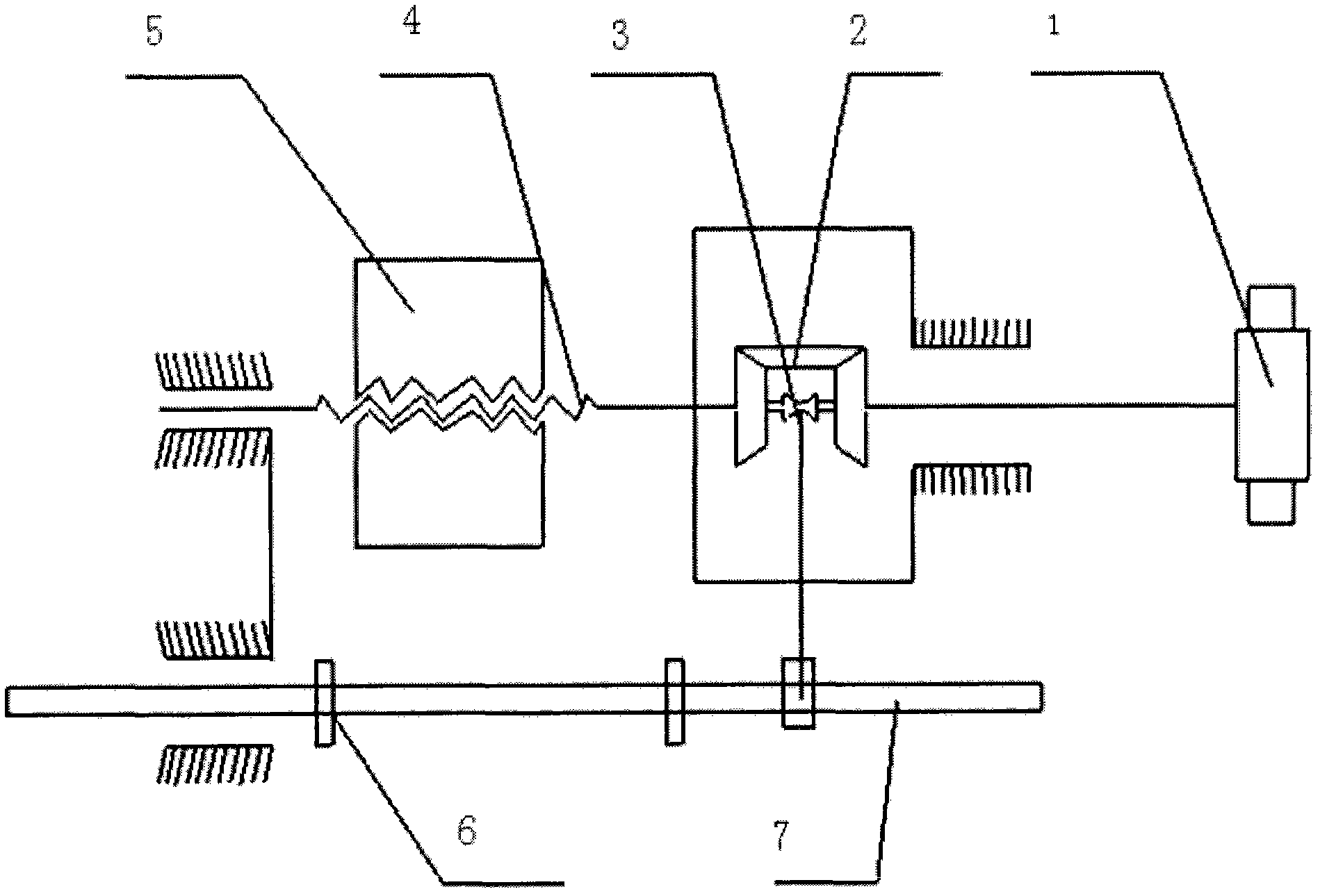
[0060] The lead screw rowing system of the drilling drawworks that the present invention relates to is as figure 1 As shown, it is mainly composed of a lead screw 4, a driving device 1 connected to the lead screw 4, and a nut 5 set on the lead screw 4, and a reversing device is also set on the lead screw 4.

[0061] The driving device 1 is a pull belt pulley.

[0062] Limiting blocks 6 are respectively arranged at both ends of the screw 4 .

[0063] The reversing device is mainly composed of a bevel gear 2 installed on the lead screw 4 and a reversing slider 3, and the bevel gear 2 and the reversing slider 3 are meshed.

[0064] The reversing slider 3 is connected with a reversing rod 7 .

[0065] The method for arranging ropes of a lead screw based on the above-mentioned lead screw arranging system comprises the following steps:

[0066] (a) First, the driving device 1 is turned on, and the driving device 1 drives the lead screw 4 to rotate;

[0067] (b) The rotation of the


PUM


Abstract

The invention discloses a system for lead screw rope arrangement of a well drilling winch. The system is mainly composed of a lead screw (4), a driving device (1) and a nut (5), wherein the driving device (1) is connected with the lead screw (4), the nut (5) is installed on the lead screw (4) in a sleeved mode, and a reversing device is installed on the lead screw (4) in a sleeved mode. The invention further discloses a method for the lead screw rope arrangement based on the system for the lead screw rope arrangement. According to the system and the method for the lead screw rope arrangement of the well drilling winch, structure is compact, machining is easy, a transmission ratio of the lead screw rope arrangement is standard, the rope arrangement is relatively even, dense, simple and direct, and installing is convenient.

Description


Claims


Application Information

Patent Timeline
Owner 晋兆建
Why Eureka
Try Eureka