Water-cooling heat dissipation substrate

A water-cooled heat dissipation and substrate technology, used in electrical components, electrical solid devices, circuits, etc., can solve the problems of large volume, poor heat dissipation performance, complex structure, etc., and achieve the effect of small size, good cooling performance, and high integration.

Active Publication Date: 2013-06-05
CRRC YONGJI ELECTRIC CO LTD
View PDF2 Cites 3 Cited by
  • Summary
  • Abstract
  • Description
  • Claims
  • Application Information

AI Technical Summary

Benefits of technology

In this new design for an electronic component that has more efficient thermal management than previous designs it had beforehand, there are two ways to improve its efficiency: one way involves adding another fluid called cold liquids into existing channels inside or outside the circuit board itself (the inner part). Another method uses external fluids like air instead of relying on gravity flow from top down towards bottom. These methods help increase energy transfer between components effectively without requiring excessive space around them.

Problems solved by technology

Technological Problem: High Power Insulation Gate Bipolar Transistor(Inverter), commonly called HIPGA, uses highly efficient semiconductor switch components like silicone diodes, but it generates much waste heat during operation due to lack of effective thermal management techniques such as forced convection systems or liquid cools. Current solutions involve installing fans outside the system's housing, leading to bulky equipment sizes and increased complexity overall.

Method used


Image

  • Water-cooling heat dissipation substrate
  • Water-cooling heat dissipation substrate

Examples


Embodiment Construction

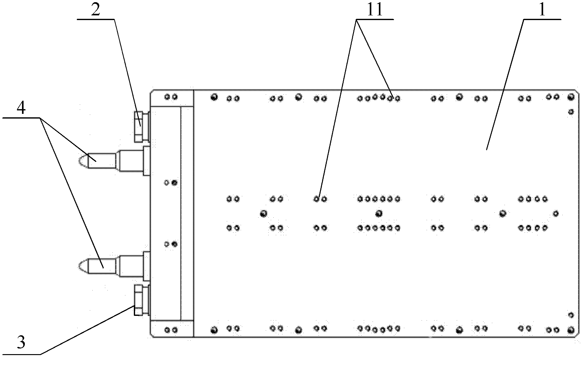
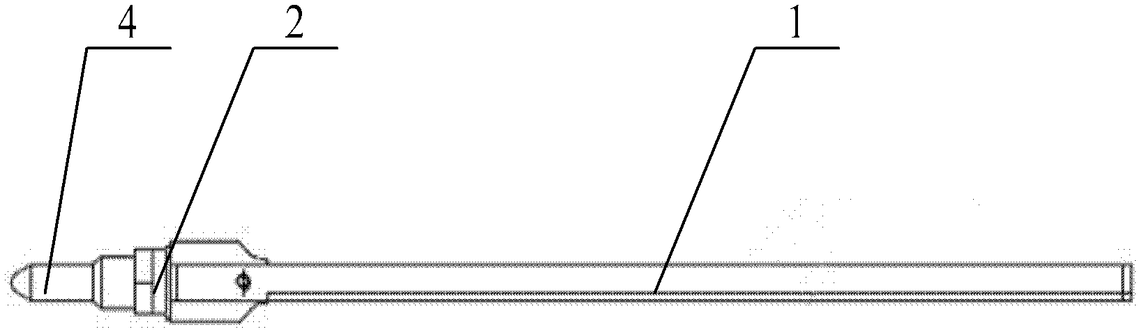
[0015] refer to figure 1 with figure 2 , figure 1 The front view of the water-cooled heat dissipation substrate provided by the embodiment of the present invention; figure 2 for figure 1 The top view of the water-cooled heat sink substrate shown.

[0016] Such as figure 1 with 2 As shown, the water-cooled heat dissipation substrate provided in this embodiment includes a main board 1 , a water inlet connector 2 and a water outlet connector 3 . The water inlet joint 2 and the water outlet joint 3 are installed on the main board 1 and communicate with the coolant channel (not shown in the figure) inside the main board 1, specifically, the water inlet joint 2 and the water outlet joint 3 are connected to the main board through threaded holes and sealant. 1 The internal coolant channel is connected.

[0017] The main board 1 has a plurality of installation holes 11 for installing power devices of the converter.

[0018] Specifically, the main board 1 is a rectangular plate s


PUM


Abstract

The invention provides a water-cooling heat dissipation substrate which comprises a main plate, a water inlet connector and a water outlet connector. The water inlet connector and the water outlet connector are arranged on the main plate and communicated with a cooling liquid channel inside the main plate. The main plate is provided with a plurality of mounting holes which are used for fixing power devices. The water-cooling heat dissipation substrate is communicated with the cooling liquid channel inside the main plate through the water inlet connector and the water outlet connector to form a cooling liquid circulation loop, heat radiated in working of the power devices is brought out, and therefore cooling of the power devices is achieved. Compared with the prior art, cooling power is large, cooling performance is good, integration level is high, and size is small. Therefore, the feasibility and the reliability of the application of the power devices are greatly improved.

Description


Claims


Application Information

Patent Timeline
Owner CRRC YONGJI ELECTRIC CO LTD
Why Eureka
Try Eureka