A cooling and heating structure

A technology for heating structures and battery packs, applied in battery pack parts, structural parts, secondary batteries, etc., can solve problems such as low single cells and inability to use efficiently

Inactive Publication Date: 2013-07-31
SHOWA DENKO KK
View PDF1 Cites 5 Cited by
  • Summary
  • Abstract
  • Description
  • Claims
  • Application Information

AI Technical Summary

Benefits of technology

This patented technology describes various technical features for improving cooling efficiency or energy utilization in electronic devices such as computers. By placing multiple small flat heat tubes on top of another larger tube containing both hot and cold liquids, they effectively transfer their lattice workings between these fluids without being affected by external factors like ambient temperatures. Additionally, this design allows for efficient cooling while minimizing power consumption compared to traditional methods involving large amounts of space. Overall, these improvements improve overall performance and functionality of electronics systems.

Problems solved by technology

This technical problem addressed in this patents relates to improving the efficiency of refrigerated systems where multiple smaller units store Lithium Ion batteries during winter months when temperatures may fall below their optimal operating range.

Method used


Image

  • A cooling and heating structure
  • A cooling and heating structure
  • A cooling and heating structure

Examples


Embodiment approach 1

[0059] This embodiment is as figure 1 and figure 2 shown.

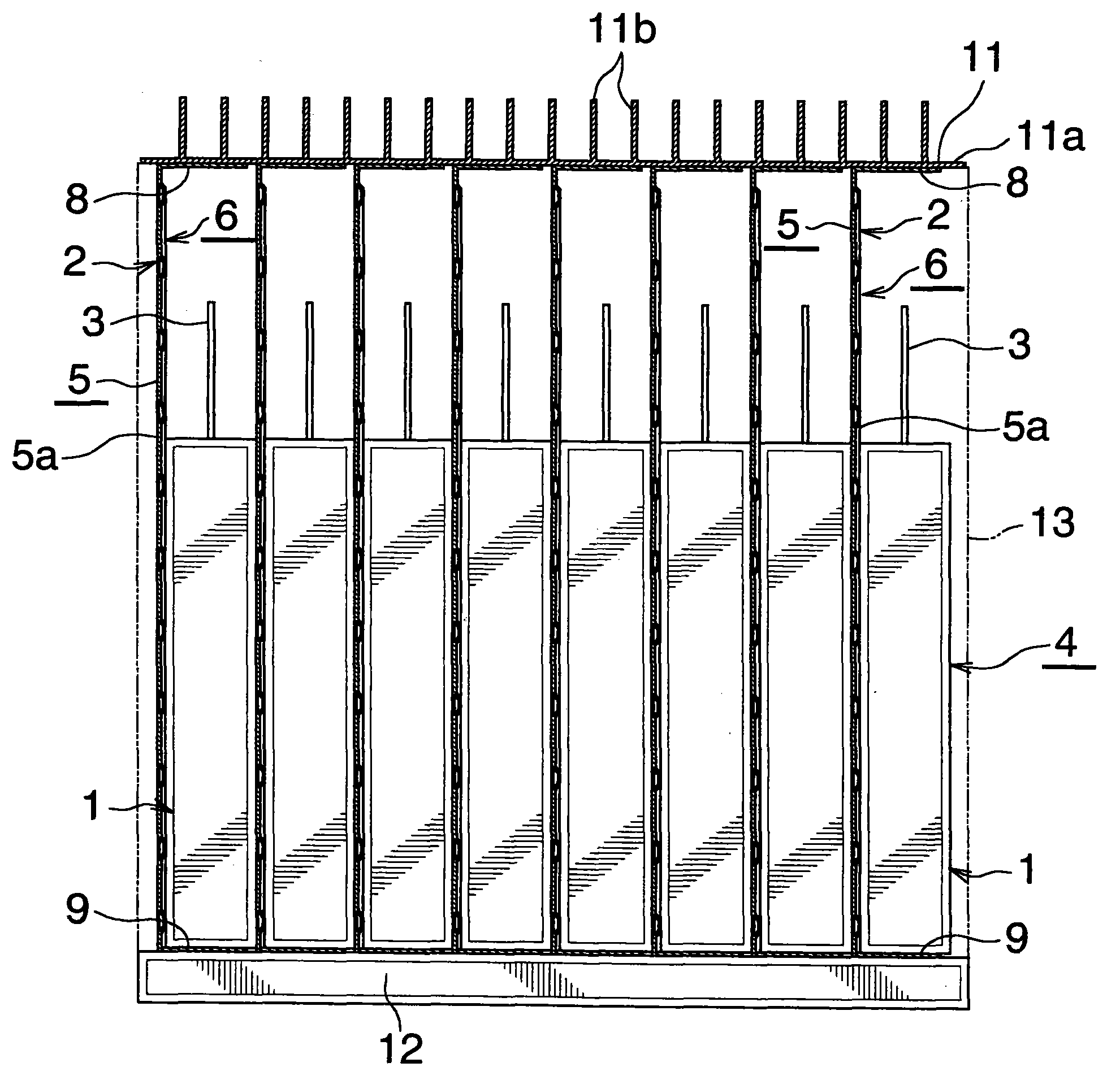
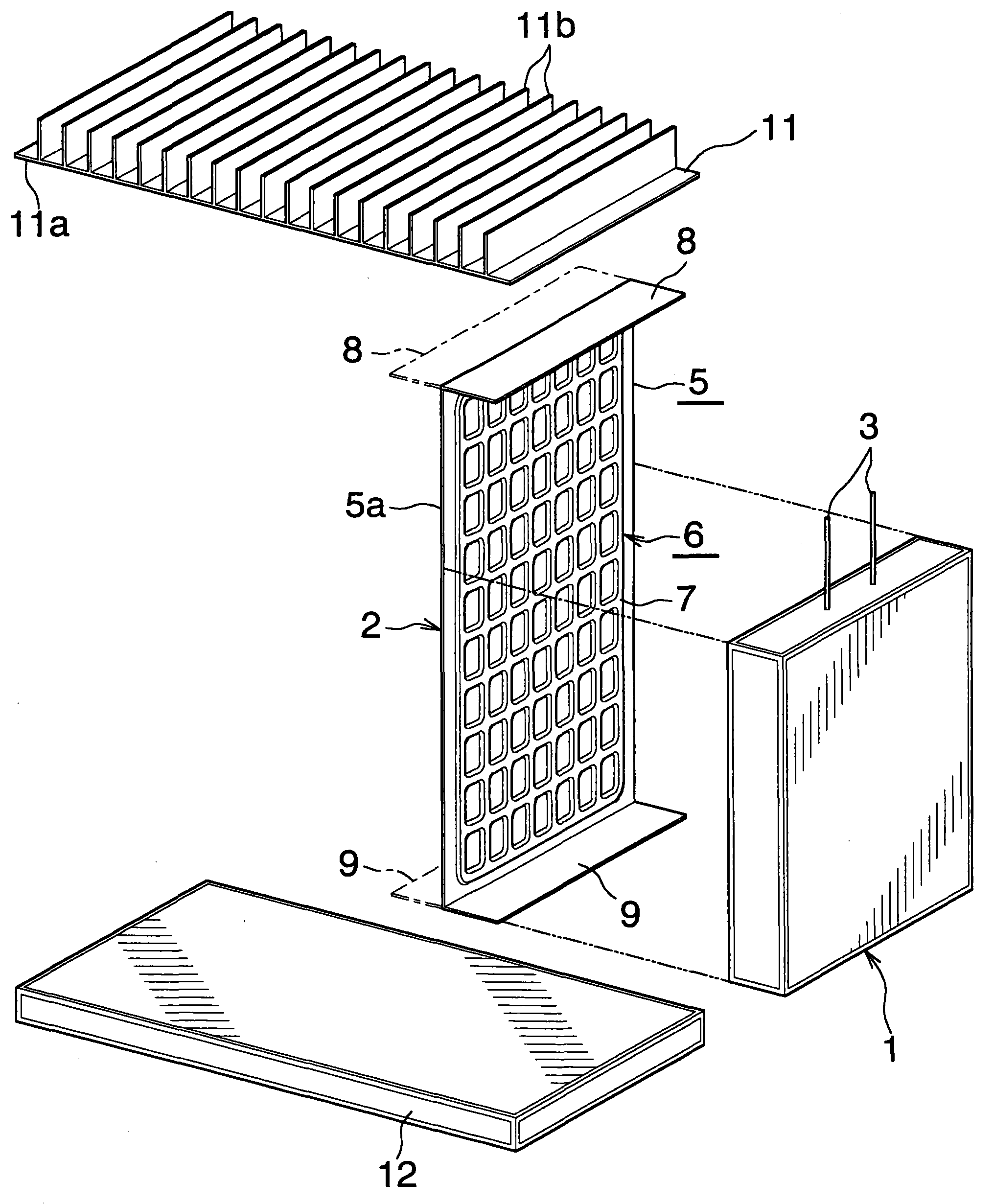
[0060] figure 1 shows the overall configuration of the cooling and heating structure of the battery pack of the present invention, figure 2 Indicates a part of it.

[0061] exist figure 1 and figure 2 In the cooling and heating structure of the battery pack, a plurality of flat rectangular parallelepiped cells 1 and a plurality of flat heat pipes 2 are stacked. Specifically, the cells 1 and the flat heat pipes 2 are vertical, and the flat plates The heat pipes 2 are stacked so that they are located between adjacent cells 1 and on the left side (outside) of the left end cell 1 . The cells 1 are in thermal contact with the flat heat pipe 2 . Although illustration is omitted, it is preferable that an electrical insulating film is interposed between the single cell 1 and the flat heat pipe 2, or an electrical insulating coating is applied to the left and right sides of the flat heat pipe 2, thereby making the singl

Embodiment approach 2

[0078] This embodiment is as Figure 7 shown.

[0079] Figure 7 The overall configuration of the cooling and heating structure of the battery pack of the present invention is shown.

[0080] exist Figure 7 In the cooling and heating structure of the battery pack, a plurality of flat rectangular parallelepiped cells 1 and a plurality of flat heat pipes 2 are stacked. Specifically, the cells 1 and the flat heat pipes 2 are horizontal, and the flat The heat pipes 2 are stacked so that they are located between adjacent cells 1 and on the lower side (outer side) of the left end cell 1 . The cells 1 are in thermal contact with the flat heat pipe 2 . Although not shown in the drawing, it is preferable that an electrical insulating film is interposed between the single cell 1 and the flat heat pipe 2, or an electrical insulating coating is applied to the left and right sides of the flat heat pipe 2, thereby making the unit An electrical insulation state is formed between the batte


PUM


Abstract

The invention provides a cooling and heating structure capable of high efficiently cooling single batteries constituting a battery set and heating the single batteries to an appropriate temperature range within short time before the battery set is used even at a severe cold area. The cooling and heating structure is equipped with multiple tabular single batteries (1) and multiple tabulate heating tubes (2) in a stacking manner. More specifically, the single batteries (1) and the tabulate heating tubes (2) are arranged in vertical shapes and at least one surface of the tabulate heating tubes (2) and the single batteries (1) are configured in stacking shape in a thermal contact manner. The top of the substrate (5) of the tabulate heating tubes (2) is higher than that of the single batteries (1). Similarly, the bottom of the substrate (5) of the tabulate heating tubes (2) is lower than that of the single batteries (1). The top of a main body part (5a) is equipped with a horizontal heat dissipating portion (8) vertical to the main body part (5a). Similarly, the bottom of the main body part (5a) is equipped with a horizontal heated portion (9) vertical to the main body part (5a).

Description


Claims


Application Information

Patent Timeline
Owner SHOWA DENKO KK
Why Eureka
Try Eureka