Shaft sleeve abrasion testing system

A wear test and shaft sleeve technology, which is applied in the direction of machine gear/transmission mechanism testing, etc., can solve the problems of single function, inability to simulate the working conditions of the shaft sleeve, low efficiency, etc., and achieve the effect of improving test efficiency

Inactive Publication Date: 2014-02-19
SANY HEAVY MACHINERY
View PDF5 Cites 0 Cited by
  • Summary
  • Abstract
  • Description
  • Claims
  • Application Information

AI Technical Summary

Benefits of technology

This patented device allows for better testing on different types of bolts used in various industries by providing an accurate simulation model with varying environmental variables like temperature or pressure during use. It includes several features: 1) it uses structures called gears to create space where the bearings are placed without touching them when they hit other parts of the equipment (such as a power transmission line); 2) it has connectors attached to both ends of the drive rods and load rods, allowing for easy replacement if needed based upon their design criteria. 3) there may have multiple connections between these components depending on how severe the impacts were experienced over its lifetime. 4) this system provides precise control over the forces applied through the actuators while measuring the results accurately compared against those measured from real-world data collected beforehand.

Problems solved by technology

This patented text discusses the issue with current methods of testing bearings during their lifetimes when they experience wearing issues caused by excessive friction. Current experiments only allow limited exposure times but may result in poor results because environmental variables like temperature also impact upon worn parts. Additionally, previous attempts were unsuccessful despite being able to accurately model work environments.

Method used


Image

  • Shaft sleeve abrasion testing system
  • Shaft sleeve abrasion testing system
  • Shaft sleeve abrasion testing system

Examples


Embodiment Construction

[0042] It should be pointed out that the description and sequence of specific structures in this section are only descriptions of specific embodiments, and should not be considered as limiting the protection scope of the present invention. In addition, the embodiments in this section and the features in the embodiments can be combined with each other under the condition of no conflict.

[0043] Please refer to Figure 1 to Figure 11 , the embodiments and various implementation modes of the present invention will be described in detail below in conjunction with the accompanying drawings.

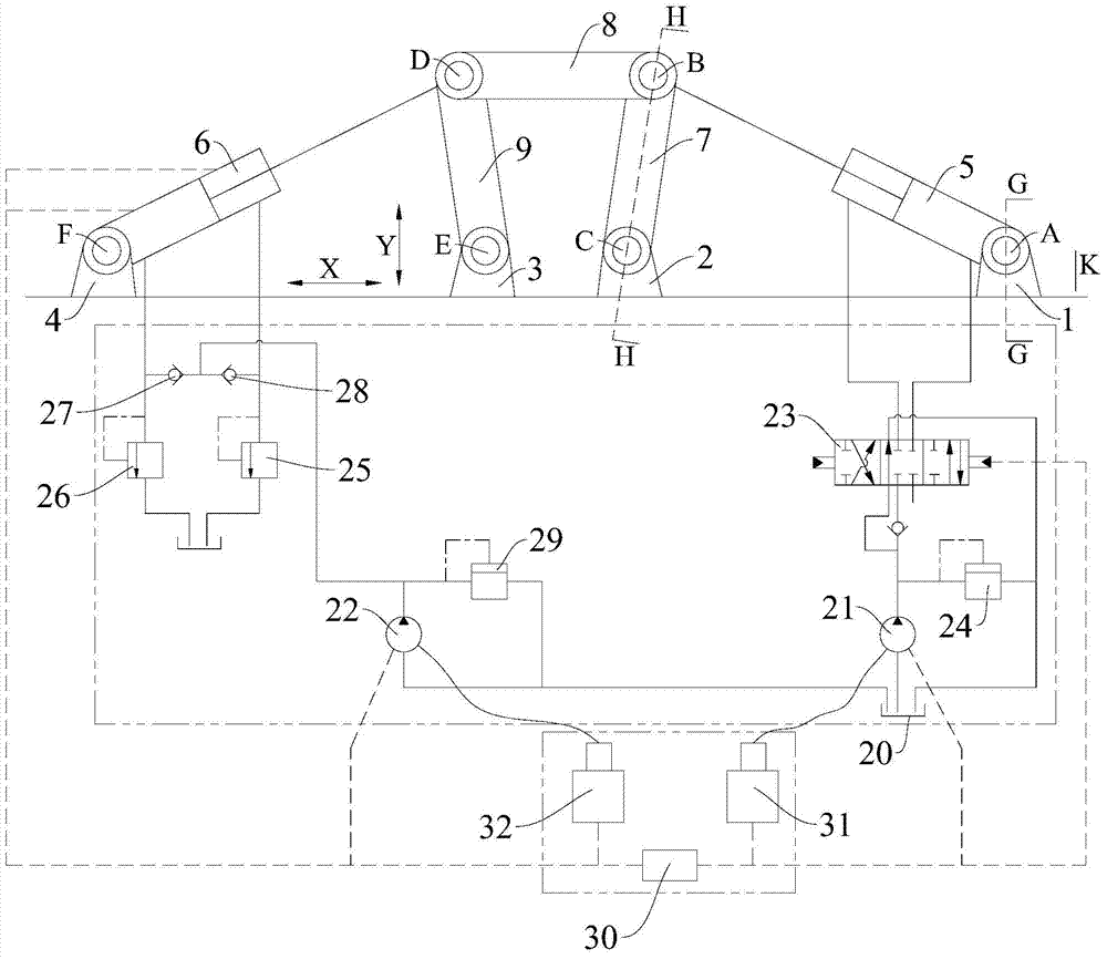
[0044] See figure 1 , and combined with figure 2 As shown, the shaft sleeve wear test system of the embodiment of the present invention is composed of three major subsystems: a mechanical system, a hydraulic system, and an electric control system.

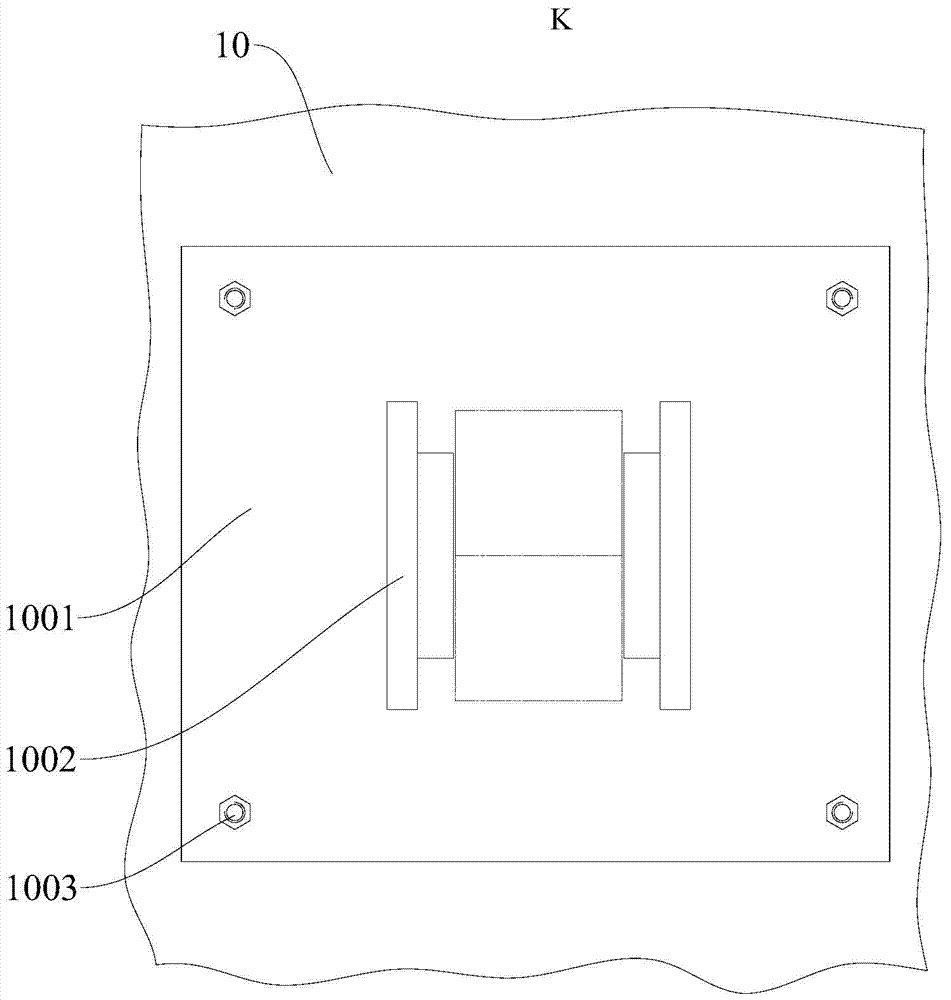
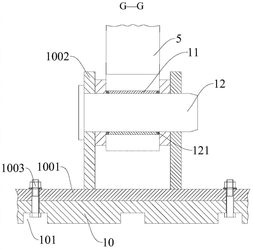
[0045] The mechanical system includes a working platform 10, a first mounting base 1, a second mounting base 2, a third mounting base 3, a fourt


PUM


Abstract

The invention discloses a shaft sleeve abrasion testing system. The shaft sleeve abrasion testing system comprises a working platform, a first installation base, a second installation base, a fourth installation base, a drive oil cylinder, a load oil cylinder, a first connection rod and a hydraulic system, wherein the first installation base, the second installation base and the fourth installation base are installed on the working platform; the first end of the drive oil cylinder is hinged to the first installation base through a first hinge point; the second end of the drive oil cylinder is hinged to the first end of the first connection rod through a second hinge point; the second end of the first connection rod is hinged to the second installation base through a third hinge point; the first end of the load oil cylinder is hinged to the fourth installation base through a sixth hinge point; the second end of the load oil cylinder is connected to the first end of the first connection rod; the hinge points are located on the same plane; each hinged position is provided with a shaft sleeve and a pin shaft; the hydraulic system is used for supplying hydraulic oil for the stretching of the drive oil cylinder and the stretching of the load oil cylinder. The shaft sleeve abrasion testing system can simulate the abrasion condition of the shaft sleeves under the actual working condition, and improve the testing efficiency.

Description


Claims


Application Information

Patent Timeline
Owner SANY HEAVY MACHINERY
Why Eureka
Try Eureka