Short-distance multi-channel video transmission method and device

A multi-channel video and transmission device technology, applied in the direction of digital video signal modification, cathode ray tube indicators, instruments, etc., can solve the problems of high hardware cost, re-construction, heavy weight, etc., to reduce hardware cost and facilitate fault maintenance , the effect of improving quality

Inactive Publication Date: 2014-03-26
GUANGDONG VTRON TECH CO LTD
View PDF5 Cites 3 Cited by
  • Summary
  • Abstract
  • Description
  • Claims
  • Application Information

AI Technical Summary

Problems solved by technology

[0003] However, the traditional video transmission method has many cables, complicated connections, and high hardware cost; in addition, because of the existing wiring, it is extremely difficult to maintain in the later stag

Method used


Image

  • Short-distance multi-channel video transmission method and device
  • Short-distance multi-channel video transmission method and device
  • Short-distance multi-channel video transmission method and device

Examples


Embodiment Construction

[0029] In order to make the object, technical solution and advantages of the present invention clearer, the present invention will be further described in detail below in conjunction with the accompanying drawings and embodiments. It should be understood that the specific embodiments described here are only used to explain the present invention, not to limit the present invention.

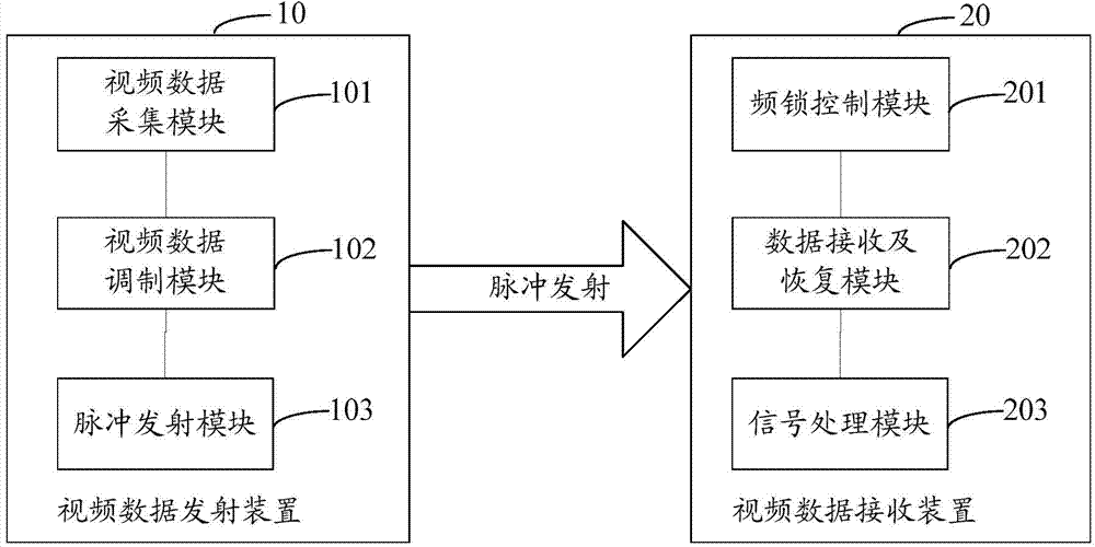
[0030] see figure 1 As shown, a short-distance multi-channel video transmission device includes: a video data transmitting device 10 and a video data receiving device 20;

[0031] The video data transmitting device 10 includes:

[0032] The video data collection module 101 is used for collecting video data to be transmitted, and decoding to obtain parallel video data. Generally from the DVI interface (Digital Visual Interface, digital video interface), the video data is in TMDS (Transition Minimized Differential Signaling, minimized transmission differential signal) format, which is decoded into par


PUM


Abstract

The invention provides a short-distance multi-channel video transmission method and device. The method includes the steps: acquiring video data and decoding the video data to obtain parallel video data at a transmitting end; acquiring video ID (identification) and performing recombination and parallel-serial conversion on the parallel video data and the video ID to obtain serial video data with video ID signals; calculating pulse transmitting frequency according to the video ID, converting the parallel video data into pulse waves according to the pulse transmitting frequency and transmitting the pulse waves; acquiring video ID and calculating pulse receiving frequency according to the video ID at a receiving end; receiving corresponding pulse waves according to the pulse receiving frequency and performing data recovery on the received pulse waves to obtain high-speed serial video data; removing the video ID signals in the high-speed serial video data and converting the high-speed serial video data into parallel video data. The hardware cost of video transmission is reduced, and signal transmission quality is improved.

Description


Claims


Application Information

Patent Timeline
Owner GUANGDONG VTRON TECH CO LTD
Why Eureka
Try Eureka