Cambered case with good heat dissipation

A chassis and arc technology, applied in the field of heat dissipation arc chassis, can solve the problems of lack of air duct guiding device, lack of novelty, and the effect of fans cannot be well exerted, so as to achieve air duct optimization, fan efficiency improvement, and heat dissipation. good performance

Inactive Publication Date: 2014-05-14
SHINAN BRANCH OF QINGDAO BLUEPRINT CULTURE COMM
View PDF7 Cites 1 Cited by
  • Summary
  • Abstract
  • Description
  • Claims
  • Application Information

AI Technical Summary

Benefits of technology

This technology helps reduce the weight at one end or improve its balance while also improving their cooling capabilities for fans that use it effectively.

Problems solved by technology

The technical problem addressed by this patented technology relates to improving cooling efficiency for computers with an improved design that allows better heat dissipation without adding extra components or increasing its size.

Method used


Image

  • Cambered case with good heat dissipation

Examples


Embodiment Construction

[0012] Below in conjunction with accompanying drawing and example the present invention will be further described:

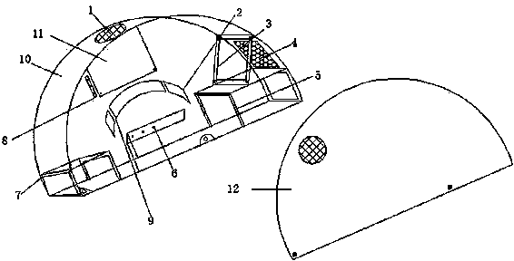
[0013] Such as figure 1 As shown, the heat dissipation arc chassis includes: ventilation net 1, baffle plate 2, fan fixing frame 3, honeycomb ventilation net 4, optical drive fixing bracket 5, hard disk fixing bracket 6, power supply fixing bracket 7, expansion card fixing platform 8, hard disk connection The wire passes through the port 9, the main body of the case 10, the main board fixing platform 11 and the side cover 12 of the case. The power supply fixing frame 7, the expansion card fixing platform 8 and the main board fixing platform 11 are fixed in the inner cavity of the chassis main body 10 by screws, the side cover 12 of the chassis is connected with the chassis main body 10 by screws, and the honeycomb ventilation net 4 is inlaid on the surface of the chassis main body.

[0014] Preferably, the chassis body is arc-shaped.

[0015] Preferably, the baff


PUM


Abstract

The invention relates to a cambered case with good heat dissipation. The cambered case comprises a vent net, baffles, a fan fixing frame, a honeycomb vent net, a CD driver, a hard disk fixing frame, a power fixing frame, an expansion card holder, a hard disk connecting wire via, a case body, a mainboard holder and a case side cover. The vent net is embedded on the surface of the case body, the baffles, the fan fixing frame, the CD driver, the hard disk fixing frame, the power fixing frame, the expansion card holder and the mainboard holder are fixed in an inner cavity of the case body through screws, the case side cover is connected with the case body through screws, and the honeycomb vent net is embedded on the surface of the case body. The center of gravity of the case is lowered so that the case is more stable, air ducts are optimized, fan efficiency is improved, and heat dissipation is improved.

Description


Claims


Application Information

Patent Timeline
Owner SHINAN BRANCH OF QINGDAO BLUEPRINT CULTURE COMM
Why Eureka
Try Eureka