Multistation hydraulic group control energy-saving technology

A hydraulic and technical technology, applied in the field of group control energy-saving transformation, can solve the problems of large space occupied by the central hydraulic station, low energy-saving efficiency, high energy consumption of large horse-drawn carts, etc., to reduce system internal leakage loss, reduce system pressure, Effect of reducing no-load power consumption

Inactive Publication Date: 2014-07-23
何荣志
View PDF11 Cites 2 Cited by
  • Summary
  • Abstract
  • Description
  • Claims
  • Application Information

AI Technical Summary

Problems solved by technology

[0003] This kind of single equipment, the current situation is that each machine tool has its own independent hydraulic system, and there is almost no connection between the hydraulic systems of each machine tool, and the installed power of each hydraulic station motor is output according to its working pump The maximum flow and pressure requirements are used for configuration, but in actual work requirements, in most of the time, the flow or pressure requirements may be far less than the maximum installed capacity, resulting in serious high energy consumption of large horse-drawn vehicles
[0004] In order to overcome the above shortcomings, there is already a patented technology of "A Hydraulic Group Control Energy Saving System" (Application No.: 2012100097372.1), which can gather many hydraulic stations together to carry out energy saving transformation. This technology provides us with great convenience; However, there are still many inconveniences in the implementation of this technology in some occasions. Its main disadvantage is that the central hydraulic station that requires centralized energy supply takes up a lot of space, and its use in some places will be strictly limited by space. Furthermore, such a transformation, Due to the large amount of newly added equipment and the large amount of renovation work, the input cost is relatively high
[0005] Another popular energy-saving transformation technology for hydraulic stations is to use servo motor or variable frequency speed regulation motor control technology to adjust the output flow of the working pump, which reduces the no-load loss of the motor to a certain extent. This technology can indeed play a certain role. energy-saving effect, but there are unfavorable factors such as low energy-saving efficiency and high investment cost for one-time transformation

Method used


Image

  • Multistation hydraulic group control energy-saving technology
  • Multistation hydraulic group control energy-saving technology
  • Multistation hydraulic group control energy-saving technology

Examples


Example Embodiment

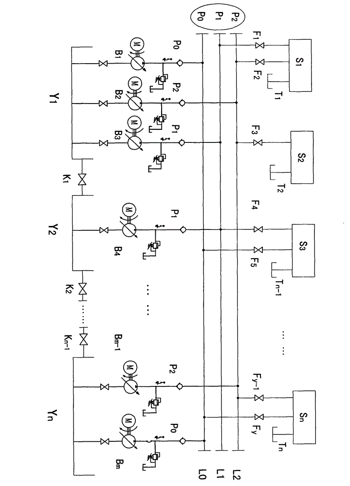
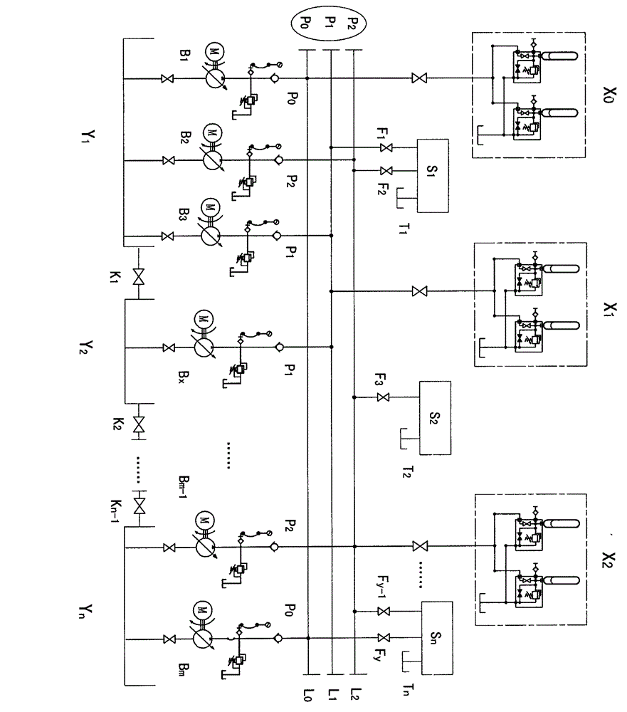
[0020] 1. Single equipment multi-hydraulic station networking mode

[0021] In a certain area, all or part of the group equipment is connected to the hydraulic system for energy-saving transformation. The functions and structures of these group equipment can be the same or different.

[0022] 1.1, hydraulic station fuel tank networking mode

[0023] Connect the oil tanks of all the single equipment hydraulic stations that need to be modified. Generally, the bottom or upper part of the oil tank is connected by pipes, so that the hydraulic oil in each oil tank can circulate freely with each other. It is important to pay attention to the highest position of each oil tank. The allowable liquid level should be roughly in the same plane, and the minimum allowable liquid level at the bottom of the tank should not be too different to prevent the high-level tank from being emptied or the low-level tank from being filled and overflowing. Each tank is filled with the same hydraulic oil. In short,


PUM


Abstract

The invention relates to a multistation hydraulic group control energy-saving technology. According to the multistation hydraulic group control energy-saving technology, a plurality of single device hydraulic stations in some region perform networking operation, oil tanks of the single device hydraulic stations are communicated with each other, all the hydraulic stations can output a few pressure sources, power sources with the same pressure are collected together through main pipelined, power sources with different pressures operate in different pipelines, and all the hydraulic stations can output various power resources with different pressure grades in a unified mode. Hydraulic energy storage stations with a certain capacity can be arranged on the pressure main pipelines and cooperate with the hydraulic stations to work, starting-up capacity of an electric motor-pump can be reduced, and the energy saving rate of a hydraulic system performing networking operation reaches 60 percent to 80 percent.

Description


Claims


Application Information

Patent Timeline
Owner 何荣志
Why Eureka
Try Eureka