Brake cable support structure in saddle type vehicle

A saddle-riding vehicle and support structure technology, applied to bicycle brakes, bicycle accessories, etc., can solve the problems of difficulty in ensuring the inclination angle, large-scale locking structure, and difficulty in ensuring the minimum ground height, so as to ensure the inclination angle, structure and The effect of shape simplification

Active Publication Date: 2014-08-27
HONDA MOTOR CO LTD
View PDF3 Cites 0 Cited by
  • Summary
  • Abstract
  • Description
  • Claims
  • Application Information

AI Technical Summary

Problems solved by technology

However, when the brake cable is held by the clamp or the stay as disclosed in the above-mentioned Patent Document 1, a structure is required for locking and positioning the clamp or the stay relative to the power unit so that Locking the brake cable in the desired direction or position easily leads to an increase in the size of the locking structure
In addition, in the case where the brake cable must be locked in such a way as to bend it, the rigidity of the clamp or stay must also be ensured, so there is a

Method used


Image

  • Brake cable support structure in saddle type vehicle
  • Brake cable support structure in saddle type vehicle
  • Brake cable support structure in saddle type vehicle

Examples


Embodiment Construction

[0054] Embodiments of the present invention will be described with reference to the drawings. In addition, in the following description, front and rear, left and right, and up and down refer to the directions viewed from the occupant of the motorcycle.

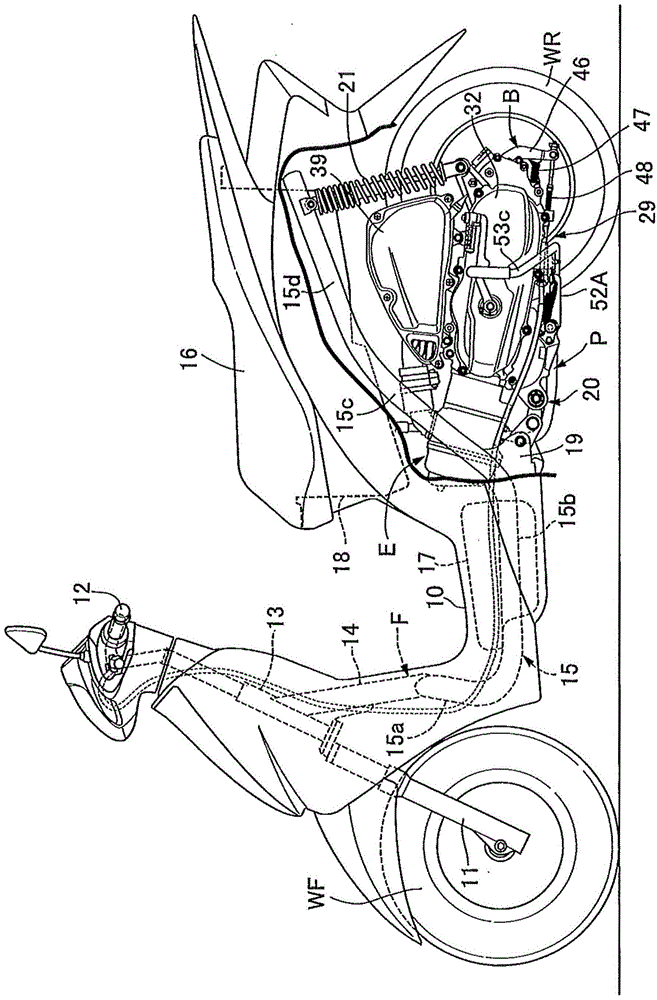
[0055] refer to Figure 1 to Figure 5 To describe the first embodiment of the present invention, first, in figure 1 Among them, the saddle-riding vehicle is a portable motorized two-wheeled vehicle having a low-floor floor 10 for a passenger seated on a passenger seat 16, and the frame F of the saddle-riding vehicle includes: Steering stem 13, which supports the front fork 11 pivotally supporting the front wheel WF and the steering handle 12 connected to the front fork 11 so as to be steerable; the downpipe 14, which extends rearward and downward from the steering stem 13; and left and right A pair of side frames 15 . . . have their front ends joined to the lower end of the down tube 14 .

[0056] The side frame 15 integrally


PUM


Abstract

The invention provides a brake cable support structure in saddle type vehicle; the brake cable is connected with a brake arm arranged on a drum brake of a rear wheel; a rear wheel shaft supports a rear end portion of a transmission housing of a swing type power unit; a middle portion, extending forwards from a lower direction of the power unit, of the brake cable is kept on a lower surface of the power unit; a main support supports the power unit in a mode in which the main support can rotate between a standup position and a containing position, so main support interference can be prevented, tilting angle can be ensued, and the middle portion of the brake cable can be supported by a simple and compact structure; a keeping portion (60) keeping the middle portion of the brake cable (48) is arranged on the lower surface of the power unit (P) in a mode in which the keeping portion is positioned above the main support (52A) in the containing position.

Description


Claims


Application Information

Patent Timeline
Owner HONDA MOTOR CO LTD
Why Eureka
Try Eureka