Admission cam shaft of engine

A technology for intake camshafts and engines, applied to engine components, machines/engines, mechanical equipment, etc., can solve problems such as low torque at low speeds, insufficient engine power performance, etc., to achieve improved torque at low speeds, performance optimization, and improved power performance effect

Inactive Publication Date: 2014-09-17
SAIC-GM-WULING AUTOMOBILE CO LTD
View PDF6 Cites 3 Cited by
  • Summary
  • Abstract
  • Description
  • Claims
  • Application Information

AI Technical Summary

Problems solved by technology

The working effect achieved by assembling it into a small gasoline engine is insufficient, mainly manifested in the fact that the low speed torque that can be achieved is low during the use of the engine, and the engine power performance is insufficient

Method used


Image

  • Admission cam shaft of engine

Examples


Example Embodiment

[0009] The present invention will be further described below in conjunction with the description of the drawings and the specific embodiments.

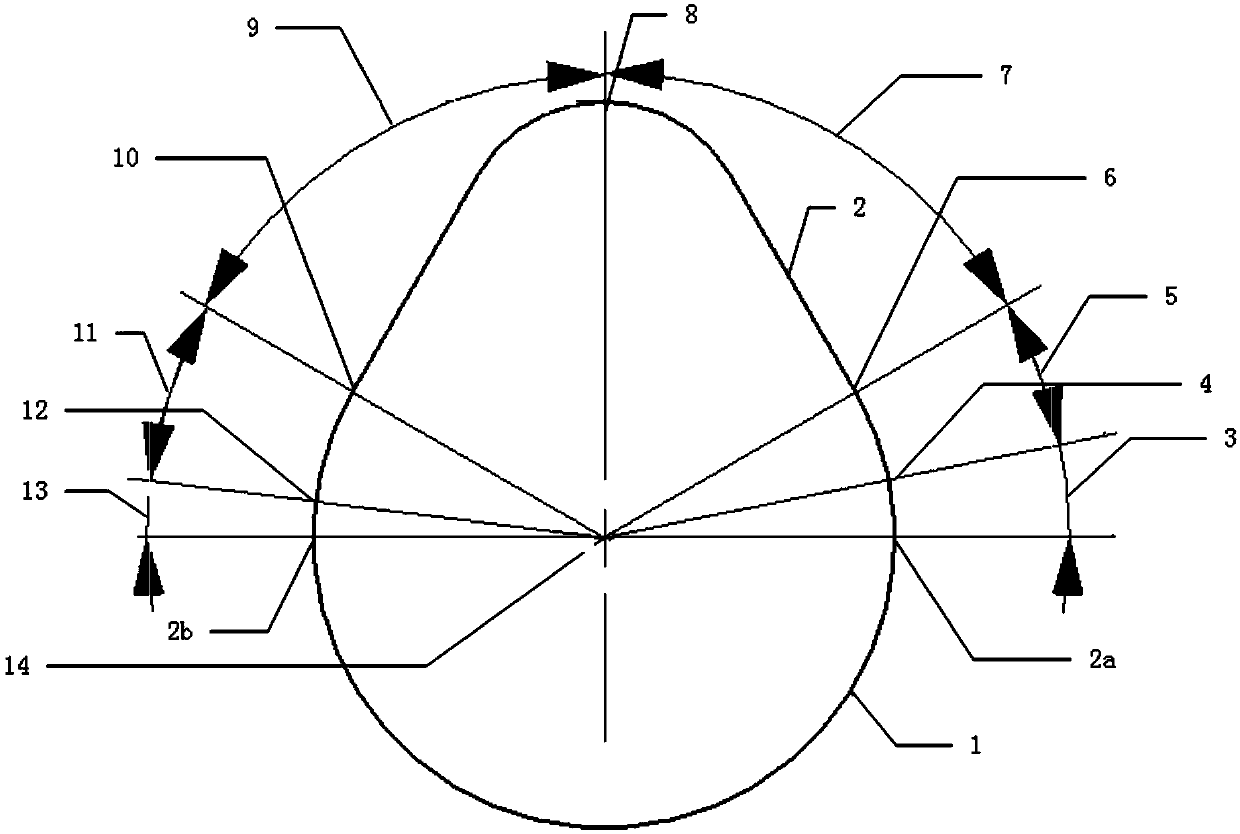
[0010] Such as figure 1 As shown, the profile of the camshaft includes a base circle (1) and a cam lobe (2). The center of the base circle (1) and the radial center of the cam lobe (2) coincide with the cam center (14) , And the two end points of the base circle coincide with the two end points of the cam peach, and the two end points of the cam peach are the opening end point (2a) and the closing end point (2b); the cam peach (2) ) Also includes the starting point of the buffer section (4), the point of completely eliminating valve clearance (6), the maximum valve lift point (8), the valve closing point (10), and the end point of closing the buffer section (12); The radius of the circle (1) is 15-17mm, the maximum lift of the cam is 7-8mm; the lift of the cam buffer section is 0.2-0.4mm; between the opening end point (2a) and the start po


PUM

PropertyMeasurementUnit
Radiusaaaaaaaaaa
Radiusaaaaaaaaaa

Abstract

The invention provides an admission cam shaft of an engine. According to the design range of the base circle radius in a molded line, the base circle radius of the cam shaft is 16 mm, the maximum lift range of the cam molded line is 8 mm, and the lift range of the buffer section of a cam is 0.29 mm. From one end of the cam shaft to the other end of the cam shaft, the opening angle between the radial center of the cam shaft and the buffer section is 3.5 degrees, the opening buffer section angle between the opening end point and the buffer section is 27.5 degrees, the valve opening section angle between the point where the valve gap is completely eliminated and the valve closing point is 59 degrees, the closing buffer section angle between the valve closing point and the closing buffer section ending point is 27.5 degrees, and the ending angle between the closing buffer section ending point and the closing end point is 3.5 degrees. The symmetrical molded line design is adopted for the opening side and the closing side of the cam type axis and the opening buffer section and the closing buffer section, the maximum acceleration of the cam can reach 0.029 mm/deg<2>, the low-rotating-speed torque of the engine is increased, the power performance of the engine is improved, and emission of harmful gas is reduced.

Description


Claims


Application Information

Patent Timeline
Owner SAIC-GM-WULING AUTOMOBILE CO LTD
Why Eureka
Try Eureka