Tubular evaporator with two ends for dividing and gas guiding

A shunt tube and evaporator technology, applied in the direction of evaporator/condenser, refrigeration components, refrigerators, etc., can solve the problems of affecting the heat transfer performance of the evaporator, the performance of the refrigeration system, and the drying of the tube, and achieve simple structure and processing. Easy assembly and energy saving effect

Inactive Publication Date: 2014-12-17
佛山市顺新电器有限公司
View PDF4 Cites 2 Cited by
  • Summary
  • Abstract
  • Description
  • Claims
  • Application Information

AI Technical Summary

Benefits of technology

This innovative technology improves how well an ice maker works by allowing for better cooling efficiency compared to previous designs that had only one end attached directly to another component or requiring multiple pipes. It also separates out liquids like water vapor while keeping them separate at both ends, increasing their contact area between these components. Additionally, it simplifies its manufacturing processes making it more cost-effective than current methods due to fewer parts needed. Overall, this new design helps reduce power consumption without compromising on any other aspects such as thermal comfort and prevention against fire hazards.

Problems solved by technology

This patented technical problem addressed by this patents relates to how to improve the efficiency with which an air conditioner uses condensers that have lower liquid levels than usual due to their design or manufacturing process issues such as causing them to become dried quickly over time when they are used at high altitudes where temperatures can be very low (-20°C).

Method used


Image

  • Tubular evaporator with two ends for dividing and gas guiding
  • Tubular evaporator with two ends for dividing and gas guiding
  • Tubular evaporator with two ends for dividing and gas guiding

Examples


Embodiment Construction

[0016] The present invention will be described in further detail below in conjunction with the accompanying drawings and specific embodiments.

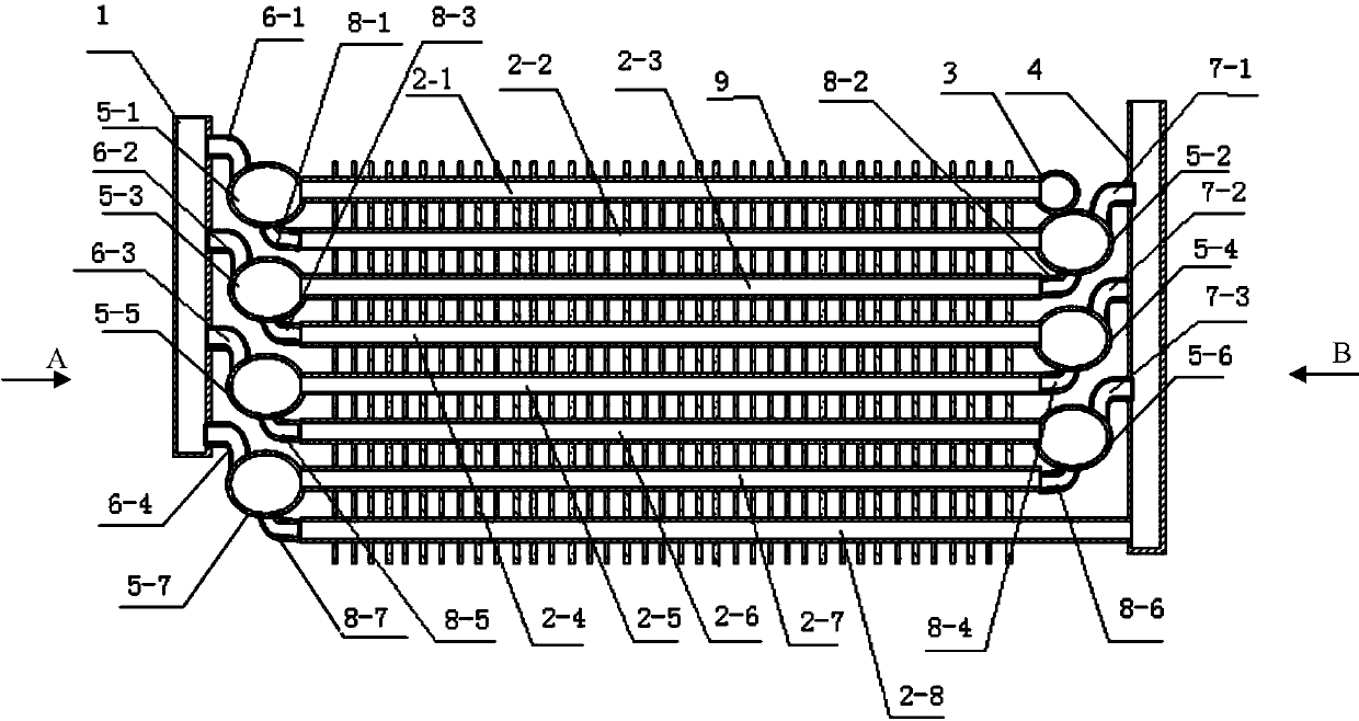
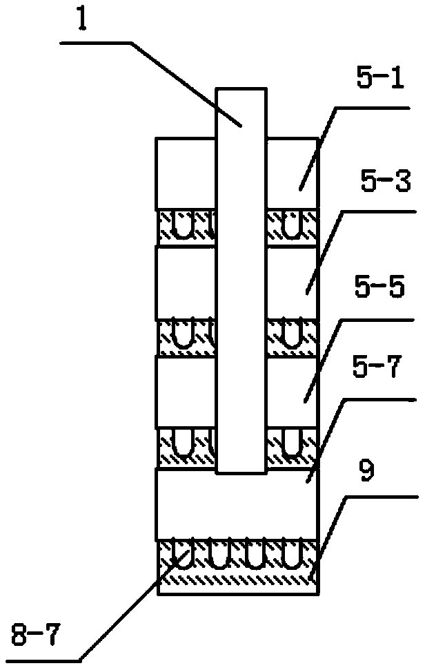
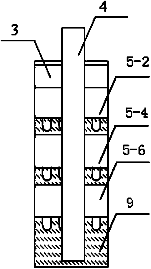
[0017] The tubular evaporator with both ends splitting and air-introduction of the present invention is a structure in which an exhaust part is added to the structure of the existing tubular evaporator. Including multiple rows of heat exchange tubes, one end of the refrigerant inlet of the heat exchange tube in the uppermost row is connected to the liquid distribution pipe, and one end of each row of the heat exchange tubes used as the refrigerant inlet is respectively connected to a liquid elbow; the last One end of the refrigerant outlet of the heat exchange tubes in the lower row is connected to the second air return pipe, and one end of the remaining heat exchange tubes in each row as the refrigerant outlet is respectively connected to a closed shunt pipe; The corresponding branch pipe is connected with the liquid elbow to form a con


PUM


Abstract

The invention discloses a tubular evaporator with two ends for dividing and gas guiding, and provides an evaporator capable of improving the heat transfer property of the evaporator and improving the performance of a refrigerating system. One end of a refrigerant inlet of a heat exchange tube in the uppermost row is connected with a liquid dividing tube, and one end, serving as a refrigerant inlet, of each heat exchange tube in other rows is connected with a liquid bend; one end of a refrigerant outlet of a heat exchange tube in the lowermost row is connected with a second gas return tube, and one end, serving as a refrigerant outlet, of each heat exchange tube in other rows is connected with a dividing tube; corresponding dividing tubes and liquid bends on the same side in adjacent rows are connected to form a communicated refrigerant flow passage; each dividing tube on one side is connected with a first gas return tube through a left gas guiding bend, and each dividing tube on the other side is connected with the second gas return tube through a right gas guiding bend. According to the evaporator, two ends of each heat exchange tube in each flow pass are respectively connected with the corresponding dividing tube, liquid bend and gas guiding bend, the wetting ratio of liquid in the tubes can be increased, the heat transfer property of the evaporator is improved and the performance of the refrigerating system is improved.

Description


Claims


Application Information

Patent Timeline
Owner 佛山市顺新电器有限公司
Why Eureka
Try Eureka