Automatic alarm room temperature on-off control valve

A technology of on-off control and automatic alarm, applied in the field of mechanical parts, can solve the problems of simple structure, unable to meet the user's connection time and frequency, and achieve the effect of preventing damage

Inactive Publication Date: 2015-03-25
天津市金超利达科技有限公司
View PDF1 Cites 0 Cited by
  • Summary
  • Abstract
  • Description
  • Claims
  • Application Information

AI Technical Summary

Problems solved by technology

This kind of ordinary control valve has a simple structure and cannot m

Method used


Image

  • Automatic alarm room temperature on-off control valve

Examples


Embodiment Construction

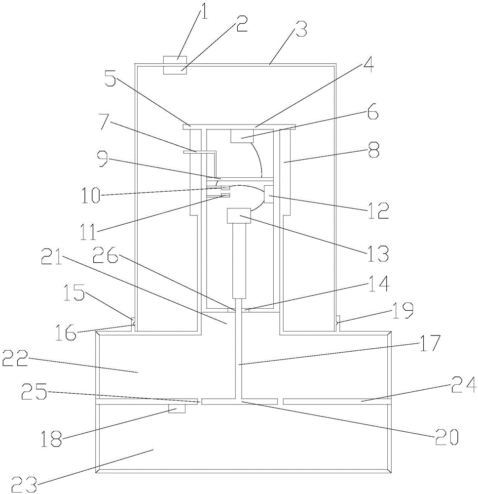
[0008] The following is attached figure 1 The present invention is further described:

[0009] In the figure: 1-alarm light, 2-flow sensor, 3-rectangular cover, 4-control box, 5-baffle plate, 6-temperature sensor, 7-signal receiver, 8-valve body, 9-control circuit board, 10-Moving contact, 11-Static contact, 12-Motor, 13-Cylinder, 14-Sealing ring, 15-Limiting plate, 16-Protrusion, 17-Stem, 18-Flow controller, 19-Concave Groove, 20-spool, 21-control chamber, 22-input chamber, 23-output chamber, 24-partition plate, 25-pass groove, 26-through hole.

[0010] The present invention includes a valve body 8, the upper part of the valve body 8 is provided with a control chamber 21, the lower part of the valve body 8 is provided with an input chamber 22 and an output chamber 23, and a partition 24 is arranged between the input chamber 22 and the output chamber 23, and the middle of the partition 24 A through groove 25 is provided, a valve core 20 is arranged in the through groove 25, a f


PUM


Abstract

The invention belongs to the field of mechanical parts, and particularly relates to an automatic alarm room temperature on-off control valve. A control box is arranged in a control bin. A temperature sensor is arranged on the top inside the control box. A control circuit board is arranged below the temperature sensor. The temperature sensor is connected with the control circuit board. A signal receiver is welded to the control circuit board and sequentially penetrates through the control box and a valve body. A fixed contact, a movable contact, a motor and a cylinder are arranged below the control circuit board. The movable contact is connected with the control circuit board and the motor and is perpendicularly located above the fixed contact. The cylinder is connected with the motor. A piston of the cylinder is connected with a valve rod which is fixed to the upper surface of a valve element. A through hole is formed in the bottom of the control box. The valve rod is arranged in the through hole. A seal ring is arranged between the valve rod and the control box.

Description


Claims


Application Information

Patent Timeline
Owner 天津市金超利达科技有限公司
Why Eureka
Try Eureka