Dynamic capacity adjusting electric reactor for filtering compensation device

A compensation device and reactor technology, applied in the direction of inductors, variable inductors, output power conversion devices, etc., can solve the problems of low adjustment accuracy and inability to realize stepless adjustment, and achieve good filtering effect and adjustment accuracy high effect

Inactive Publication Date: 2015-03-25
无锡市锡容电力电器有限公司
View PDF6 Cites 0 Cited by
  • Summary
  • Abstract
  • Description
  • Claims
  • Application Information

AI Technical Summary

Problems solved by technology

However, this adjustment method is limited by the number of taps, the

Method used


Image

  • Dynamic capacity adjusting electric reactor for filtering compensation device

Examples


Embodiment Construction

[0009] The present invention will be further described below in conjunction with drawings and embodiments. It should be understood that the specific embodiments described here are only used to explain the present invention, but not to limit the present invention. In addition, it should be noted that, for the convenience of description, only some parts related to the present invention are shown in the accompanying drawings but not the whole content. Unless otherwise defined, all technical and scientific terms used herein are related to the technology belonging to the present invention. Those skilled in the art usually understand the same meaning. The terminology used herein is for the purpose of describing specific embodiments only, and is not intended to limit the invention.

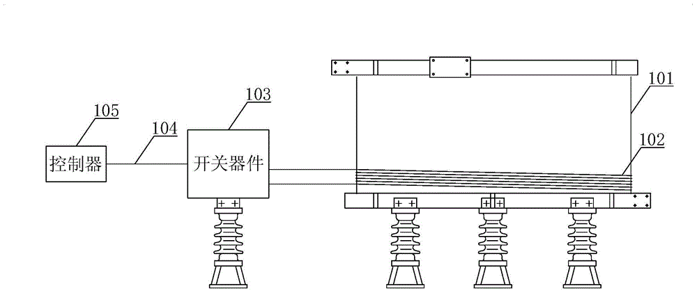
[0010] Please refer to figure 1 as shown, figure 1 The structural diagram of the dynamic capacitance-adjusting reactor used in the filter compensation device provided by the embodiment of the present inv


PUM


Abstract

The invention discloses a dynamic capacity adjusting electric reactor for a filtering compensation device. The dynamic capacity adjusting electric reactor for the filtering compensation device comprises a main coil, an auxiliary coil, a switch device, an optical fiber and a controller, wherein the auxiliary coil is connected with the switch device; the switch device is connected with the controller through the optical fiber; the controller outputs corresponding switch signals to the switch device according to a target capacity value, which is required to be adjusted, of the electric reactor; and the switch device generates current which is required to be outputted by the filtering compensation device under the control of the switch signals and outputs the current to the auxiliary coil, so that the capacity of the electric reactor is adjusted. Because the target capacity value, which is required to be adjusted, of the electric reactor corresponds to the current which is required to be outputted by the filtering compensation device, and the current generated by the switch device can be adjusted in a stepless manner according to the corresponding switch signals outputted by the controller, the capacity of the electric reactor can be dynamically adjusted in a stepless manner. The dynamic capacity adjusting electric reactor is not limited by the number of taps; the adjusting precision is high; and a high filtering effect of the filtering compensation device can be achieved.

Description


Claims


Application Information

Patent Timeline
Owner 无锡市锡容电力电器有限公司
Why Eureka
Try Eureka