An Overtight Protective Shear Ring Locking Mechanism

A technology of locking mechanism and shear ring, which is applied in the direction of fluid pressure actuating device, etc., can solve problems such as equipment failure, indentation on the surface of shaft and rod parts, and lack of limit ability, so as to achieve good clamping force and prevent damage , design reasonable effect

Inactive Publication Date: 2017-03-01
CHENGDU OUXUN TECH CO LTD
View PDF8 Cites 0 Cited by
  • Summary
  • Abstract
  • Description
  • Claims
  • Application Information

AI Technical Summary

Problems solved by technology

[0002] At present, in some pressure cylinders, such as hydraulic cylinders, pneumatic cylinders and other mechanical structures, in order to have a good positioning and sealing effect on the shaft parts on the cylinder, it is often necessary to use a shear ring device to fix the shaft parts. Clamping and positioning, but in use, it is found that when the shearing ring device is used to position the shaft parts, due to the lack of the necessary limit ability, it will often cause serious indentations on the surface of the shaft parts and damage The surface quality of the shaft and rod parts is deteriorated, and even serious equipment failure is caused in serious cases, which seriously affects the performance of the shear ring device. Therefore, in order to improve the stability of equipment operation and enhance the reliability of the shear ring device , there is an urgent need to improve the existing shearing ring device, so that it can provide reliable sealing and compression capabilities while avoiding damage to the surface of shaft parts

Method used


Image

  • An Overtight Protective Shear Ring Locking Mechanism
  • An Overtight Protective Shear Ring Locking Mechanism

Examples


Example Embodiment

[0013] In order to make the technical means, creative features, achievement goals and effects realized by the present invention easy to understand, the present invention will be further described below with reference to the specific embodiments.

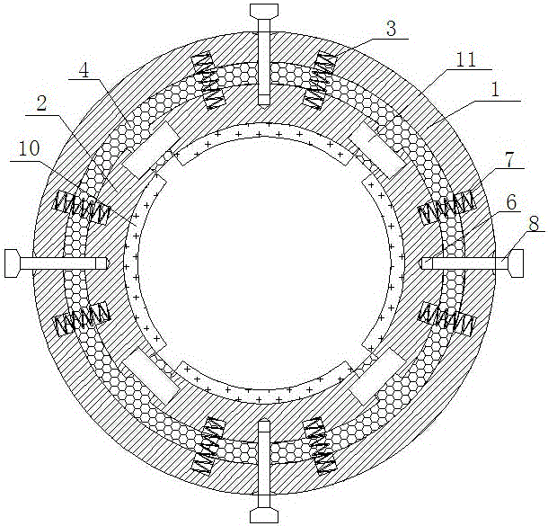
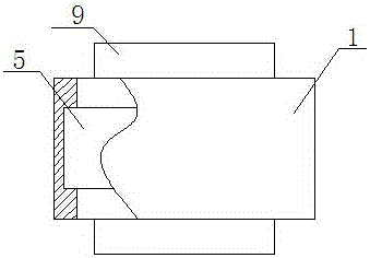
[0014] like figure 1 and 2 The above-mentioned over-tightening protection type shear ring locking mechanism includes a positioning plate 1, a pressing block 2, a return spring 3 and an elastic positioning block 4. The positioning plate 1 is cylindrical, and a position groove 5 is set on its inner surface. .

[0015] In this embodiment, the pressing blocks 2 are at least 4 and are all arc-shaped. After the pressing blocks 2 are connected in sequence, they can form a perfect circle concentrically distributed with the positioning plate 1. The pressing blocks 2 are evenly distributed on the inside the positioning groove 5 and slidingly connected with the positioning groove 5, and the middle point of the outer surface of the pressing block


PUM


Abstract

The invention relates to an over-tightening protective shear ring locking mechanism. The over-tightening protective shear ring locking mechanism comprises a positioning plate, at least four compressing blocks, reset springs and elastic positioning blocks, wherein the positioning plate is cylindrical, and a positioning groove is formed in the inner surface of the positioning plate; the compressing blocks are connected with the positioning groove in a sliding mode; the elastic positioning blocks are respectively arranged between the inner surface of the positioning groove and the outer surfaces of the compressing blocks as well as between the contact surfaces of adjacent compressing blocks; a connecting screw hole is formed in the middle point of the outer surface of each compressing block; at least one mounting hole is respectively formed in the two sides of each connecting screw hole; connecting screw holes and mounting holes are also respectively formed in the positions, corresponding to the connecting screws and the mounting holes, of the positioning groove; a driving screw rod is arranged in each compressing block through the corresponding connecting screw hole; the reset springs are mounted in the mounting holes; connecting blocks are additionally arranged on the upper end face and the lower end face of the positioning plate. On one hand, constant clamping force and good sealing capacity can be provided for axle and shaft parts, and on the other hand, the structures of the alxe and shaft parts can be effectively prevented from being damaged by too large clamping force while the alxe and shaft parts are clamped.

Description


Claims


Application Information

Patent Timeline
Owner CHENGDU OUXUN TECH CO LTD
Why Eureka
Try Eureka