Large-size liquid crystal panel detection device

A liquid crystal panel and detection device technology, applied in the direction of nonlinear optics, instruments, optics, etc., can solve the problems of low detection efficiency, poor detection effect, no alignment device, handling device, etc., achieve high detection efficiency, simple operation, The effect of high degree of automation

Active Publication Date: 2015-04-01
SUZHOU JINGLAI OPTO CO LTD
View PDF6 Cites 11 Cited by
  • Summary
  • Abstract
  • Description
  • Claims
  • Application Information

AI Technical Summary

Benefits of technology

This patented technology uses an integrated system for automatically inspecting and handling liquid crystals panels during manufacturing processes. It includes conveyers, location devices, turn-over machines, and sensors controlled through a computer program. These systems work well with low cost components such as motors or pneumatic actuators. They allow for efficient inspections without human interference while ensuring precise placement of the display elements on the panels being tested. Overall, this technology improves productivity and reduces costs compared to traditional methods like manual labor.

Problems solved by technology

This patented technical problem addressed by this patents relates to improving the accuracy and reliability of inspecting small liquid crystals (LC) panels with multiple angled views or other orientations without requiring manual adjustment.

Method used


Image

  • Large-size liquid crystal panel detection device
  • Large-size liquid crystal panel detection device
  • Large-size liquid crystal panel detection device

Examples


Embodiment Construction

[0027] The present invention will be further described in detail below in conjunction with the accompanying drawings and specific embodiments to facilitate a clear understanding of the present invention, but they do not limit the present invention.

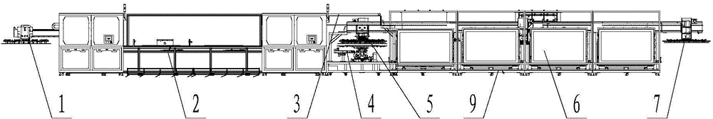
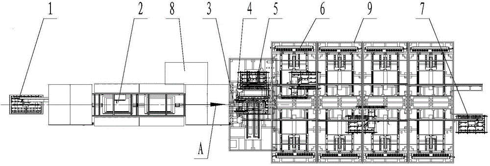
[0028] Such as figure 1 , figure 2 As shown, the present invention comprises a frame 9, on which the second feeding device 1, the assembly line device 2, the first feeding device 3, the turntable 5 and the turning mechanism are sequentially installed along the axial direction A, and the CCD camera moving device 4 Located under the support plate of the turntable 5, the turning mechanism includes a plurality of turning devices 6 installed on the frame 9 and symmetrically distributed on both sides of the axial direction A. Guide rails 94 are respectively provided on the two guide rails, and a plurality of pick-and-place devices 7 that can move along the slide rails are respectively installed. The turntable 5 is movably installed on th


PUM


Abstract

The invention belongs to the technical field of liquid crystal panel detection and particularly relates to a large-size liquid crystal panel detection device. The large-size liquid crystal panel detection device comprises a machine frame, wherein a material conveying device, a CCD (Charge Coupled Device) camera moving device, a rotary table, material taking and placing devices and a controller are mounted on the machine frame; the material conveying device, the rotary table and an overturning mechanism are sequentially mounted on the machine frame in the axial direction; the CCD camera moving device is positioned below a supporting plate of the rotary table; the overturning mechanism comprises a plurality of overturning devices which are mounted on the machine frame, are positioned on two sides of the axial direction and are symmetrically distributed; a guide rail is axially arranged at the top of each of the overturning devices on the two sides of the axial direction on the machine frame; the material taking and placing devices capable of moving along sliding rails are mounted on the two guide rails respectively. The streamlined detection device is adopted, the working state of each device is controlled by the controller, transporting and overturning of a liquid crystal panel can be controlled, and the whole detection device is high in automation degree, easy to operate and high in detection efficiency.

Description


Claims


Application Information

Patent Timeline
Owner SUZHOU JINGLAI OPTO CO LTD
Why Eureka
Try Eureka