Lightning protection socket strip with emergency lamps
A technology of emergency lights and plug-in strips, which is applied to the parts of the connection device, electrical components, coupling devices, etc., and can solve the problem of lightning protection plug-in strips without emergency lights and fixing devices
- Summary
- Abstract
- Description
- Claims
- Application Information
AI Technical Summary
Problems solved by technology
Method used
Image

Examples
Embodiment 1
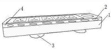
[0012] In order to overcome the defect that the existing lightning protection plug-in strips do not have emergency lights and fixing devices, this embodiment provides a figure 1 The shown lightning protection plug-in strip with emergency lights includes a housing 1, a socket provided on the housing 1 and a circuit provided inside the housing 1, and a strobe light area 4 is provided on the side of the housing 1 , the strobe light area 4 is provided with at least six strobe emergency lights 2 for providing lighting prompts during emergency power failure.
Embodiment 2
[0014] On the basis of Embodiment 1, this embodiment is also provided with two rubber suction cups 3 on the back of the housing 1, which can be adsorbed to walls, desktops, floors, etc., to prevent knocking over and breaking. And the strobe emergency light 2 is powered by the battery in the battery compartment arranged on the housing 1 , and the battery in the battery compartment is connected to the circuit inside the housing 1 . When the normal power supply is turned on, the battery in the battery compartment is charged. When a lightning strike occurs and the power is cut off, the backup power supply (battery) automatically supplies power to the strobe emergency light and provides lighting reminders.
[0015] In summary, it is not difficult to see that when the lightning protection plug-in strip with emergency lights provided by the above embodiments is in use, the battery in the battery compartment is charged when the normal power supply is turned on at ordinary times. , The ba
PUM
 Abstract
Description
Claims
Application Information
 - R&D Engineer
- R&D Manager
- IP Professional
- Industry Leading Data Capabilities
- Powerful AI technology
- Patent DNA Extraction
Browse by: Latest US Patents, China's latest patents, Technical Efficacy Thesaurus, Application Domain, Technology Topic.
© 2024 PatSnap. All rights reserved.Legal|Privacy policy|Modern Slavery Act Transparency Statement|Sitemap