Crosswind yaw control method and system for wind generating set and related components

A wind turbine and yaw control technology, which is applied in the control of wind turbines, wind turbines, and control system uses, etc., can solve problems such as blade stuck, speed increase, safety accidents, etc., to reduce the speed of the impeller and reduce the sweep. area, the effect of improving safety

Active Publication Date: 2021-04-02
CSIC CHONGQING HAIZHUANG WINDPOWER EQUIP
View PDF14 Cites 0 Cited by
  • Summary
  • Abstract
  • Description
  • Claims
  • Application Information

AI Technical Summary

Benefits of technology

This patented technology provides an improvement over existing methods for controlling the movement or rotation of rotor blade during high-speed operations such as weather conditions where there may be sudden changes in air pressure caused by rain or snow falling on the surface of the tower's structure. By allowing the bladed part of each fan blade to move backward without being blocked with debris, this improves its efficiency while still maintaining safe flight through extreme temperatures.

Problems solved by technology

This technical issue addressed during designing for safe operation at high speeds caused by overheat or other factors affects the blade movement within the rotor system of a wind generator (WG).

Method used


Image

  • Crosswind yaw control method and system for wind generating set and related components
  • Crosswind yaw control method and system for wind generating set and related components

Examples


Embodiment Construction

[0040] The following will clearly and completely describe the technical solutions in the embodiments of the application with reference to the drawings in the embodiments of the application. Apparently, the described embodiments are only some of the embodiments of the application, not all of them. Based on the embodiments in this application, all other embodiments obtained by persons of ordinary skill in the art without making creative efforts belong to the scope of protection of this application.

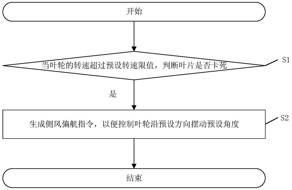
[0041] Please refer to figure 1 , figure 1 It is a flow chart of a method for controlling crosswind yaw of a wind power generating set provided in an embodiment of the present application. The crosswind yaw control method of the wind generating set includes the following steps:

[0042] Step S1, when the rotational speed of the impeller exceeds the preset rotational speed limit, it is judged whether the blade is stuck.

[0043] Specifically, the rotational speed of the impeller is a


PUM


Abstract

The invention discloses a crosswind yaw control method and system for a wind generating set and related components. The crosswind yaw control method comprises the following steps that when the rotating speed of an impeller exceeds a preset rotating speed limit value, whether blades are stuck or not is judged; if yes, a crosswind yaw instruction is generated so that the impeller can be controlled to swing by a preset angle in the preset direction. According to the crosswind yaw control method for the wind generating set, crosswind yaw operation is conducted under the conditions that the wind generating set is over-speeding and the blades are stuck, the impeller of the wind generating set is prevented from directly facing the wind direction, then the situation that the rotating speed of thewind generating set is continuously increased in emergency is avoided, and safety is improved.

Description


Claims


Application Information

Patent Timeline
Owner CSIC CHONGQING HAIZHUANG WINDPOWER EQUIP
Why Eureka
Try Eureka