Electronic element stamping raw material feeding clamping mechanical hand and clamping method thereof

A technology of electronic components and manipulators, which is applied in the field of clamping manipulators for stamping raw materials of electronic components, can solve the problems of easy falling off of workpieces, insufficient clamping force, and easy extrusion of workpieces, etc. Force area, solve vulnerable effects

Active Publication Date: 2015-05-13
WUHU ANPU ROBOT IND TECH RES INST
View PDF8 Cites 3 Cited by
  • Summary
  • Abstract
  • Description
  • Claims
  • Application Information

AI Technical Summary

Problems solved by technology

[0004] However, the commonly used industrial robots now have only one pair of claws. When grabbing the raw material of the metal casing of electronic components, the clamping force is too large, which easily squeezes the workpiece and damages the workpiece.
If the clamping force is not strong enough, the workpiece will also fall off from the gripper of the manipulator, breaking the workpiece
[0005] China's patent application number is ZL201110293356.5, which discloses a clamping and positioning pneumatic gripper, which discloses a clamping and positioning pneumatic gripper; comprising a motor 1, a fixed rod 1, a cylinder 1, a fixed baffle 1, Motor II, Fixed Rod II, Rotating Plate, Cylinder II, Cylinder III, Fixed Baffle II, Motor III, Gripper I, Cylinder IV, Fixed Baffle III, Fixed Rod III, Pressure Sensor, Cylinder V, Cyl

Method used


Image

  • Electronic element stamping raw material feeding clamping mechanical hand and clamping method thereof
  • Electronic element stamping raw material feeding clamping mechanical hand and clamping method thereof
  • Electronic element stamping raw material feeding clamping mechanical hand and clamping method thereof

Examples


Embodiment Construction

[0027] In order to make the technical means, creative features, goals and effects achieved by the present invention easy to understand, the present invention will be further described below in conjunction with specific illustrations.

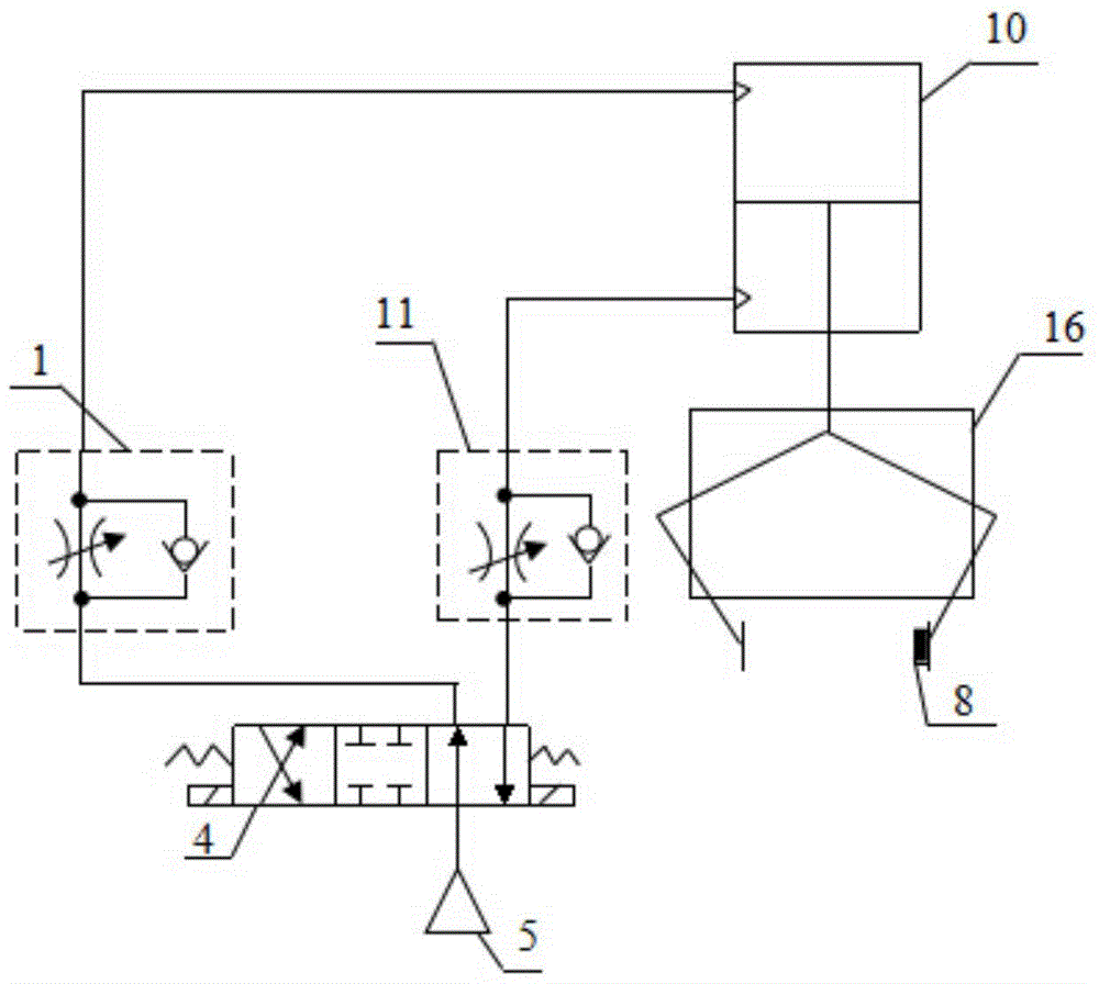
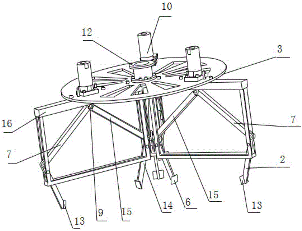
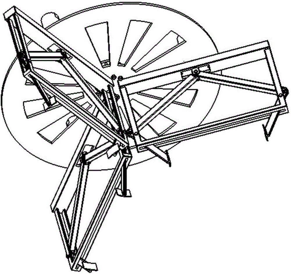
[0028] Such as Figure 1 to Figure 9 As shown, a manipulator for feeding and clamping electronic component stamping raw materials includes a mounting plate 3, and three cylinders 10 are uniformly installed on the upper end surface of the mounting plate 3, and the distances from the cylinders 10 to the axis of the mounting plate 3 are the same. The axis of the cylinder 10 is parallel to the normal line of the mounting plate 3, and the air inlet and the air outlet of the cylinder 10 are respectively connected with a throttle valve I1 and a throttle valve II11, see figure 1 , the other ends of the throttle valve I1 and the throttle valve II11 are connected with an electromagnetic reversing valve 4 , and the electromagnetic reversing valve 4 is connect


PUM


Abstract

The invention relates to an electronic element stamping raw material feeding clamping mechanical hand and a clamping method thereof, and belongs to the technical field of industrial robots. The mechanical hand comprises three supports which are distributed on a mounting plate, wherein the included angles between the supports are 120 degrees; each support is provided with a cylinder, the shaft end of each cylinder is connected with a connecting rod I and a connecting rod II, the lower ends of the connecting rods I and the lower ends of the connecting rods II are connected with connecting rods III and connecting rods IV which are all fixedly hinged to the supports, an inner arc plate and an outer arc plate are arranged at the lower end of each connecting rod III and the lower end of each connecting rod IV respectively, and force sensors are mounted on the outer arc plates. The clamping method of the mechanical hand comprises the following steps of locating, clamping and carrying. The three sets of inner arc plates and outer arc plates are adopted to grab workpieces at the same time, based on the principle that a plane is defined by three points, the workpiece grabbing process is more stable and reliable and more precise in locating, loads of all claws are greatly lowered, and the problems that in the feeding process, electronic element metal outer shell stamping parts are prone to being damaged and easily fall off are solved.

Description


Claims


Application Information

Patent Timeline
Owner WUHU ANPU ROBOT IND TECH RES INST
Why Eureka
Try Eureka