Lifting device for garbage compactor

A technology of garbage compressor and lifting device, which is applied in the direction of garbage conveying, garbage collection, storage device, etc., can solve the problems of long working stroke, large working space, and high operating cost, and achieves reduced working pressure, stable unloading operation, and reduced operating costs. The effect of production costs

Inactive Publication Date: 2017-09-29
SICHUAN NANJUN AUTOMOBILE GROUP
View PDF7 Cites 0 Cited by
  • Summary
  • Abstract
  • Description
  • Claims
  • Application Information

AI Technical Summary

Problems solved by technology

Adopting the four-column-guided vertical lifting form, the garbage bin body is difficult to balance, the operation is not stable, the working stroke is long, and the working space is large, resulting in high cost of supporting buildings, and difficult installation and debugging; whi

Method used


Image

  • Lifting device for garbage compactor

Examples


Example Embodiment

[0019] In order to enable those skilled in the art to better understand the technical solutions of the present invention, the present invention will be further described in detail below with reference to the accompanying drawings and specific embodiments.

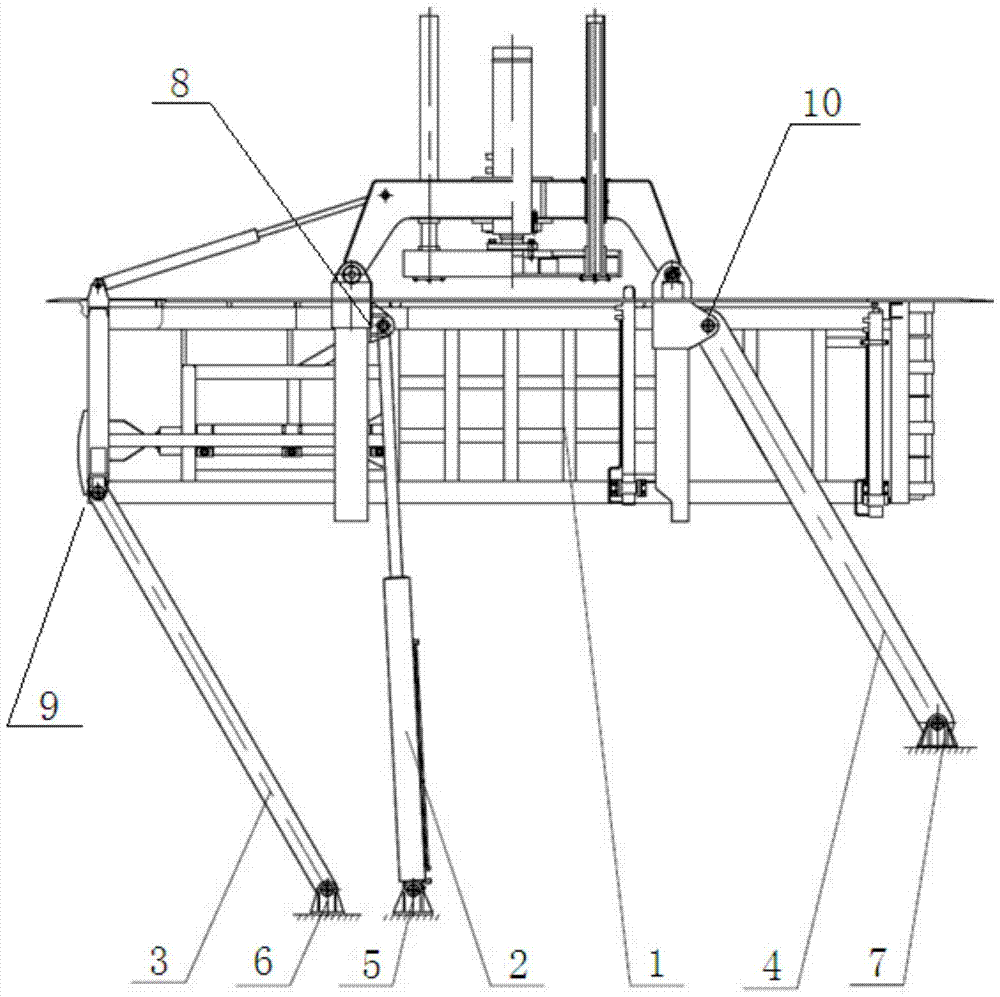
[0020] Such as figure 1 As shown, a lifting device for a garbage compressor includes a compressed garbage bin 1, a lifting cylinder 2, a front pull rod 3, a swing rod 4, a lower support for the lifting cylinder 5, a lower support for the front pull rod 6, and a lower support for the swing rod Seat 7; the box body of the compressed trash can 1 is a rectangular parallelepiped structure, the piston of the lifting cylinder 2 is hinged with the first hinge interface 8 located in the body of the compressed trash can 1, the cylinder body of the lifting cylinder 2 and the lifting cylinder The lower support 5 is hinged; one end of the front pull rod 3 is hinged with the second hinge interface 9 located in the box of the compressed trash c


PUM


Abstract

The invention discloses a lifting device for a garbage compressor. The lifting device comprises a compression garbage can, a lifting oil cylinder, a front pull rod, an oscillating rod, a lower lifting oil cylinder support, a lower front pull rod support and a lower oscillating rod support. The compression garbage can, the lifting oil cylinder, the front pull rod, the oscillating rod, the lower lifting oil cylinder support, the lower front pull rod support and the lower oscillating rod support form a four-rod mechanism. The lifting device is placed in a pit, and the occupied ground space is reduced; by the adoption of the four-rod mechanism, in the lifting state, the can body positioning effect is good, discharging operation is stable, and safety and reliability are achieved; the lifting oil cylinder directly acts in the middle of the compression garbage can, more labor is saved, and the working pressure of a hydraulic system is decreased; compared with an existing four-stand-column guiding perpendicular lifting mechanism, the stroke of the oil cylinder is effectively decreased, and the production cost is lowered.

Description


Claims


Application Information

Patent Timeline
Owner SICHUAN NANJUN AUTOMOBILE GROUP
Why Eureka
Try Eureka