A fully automatic needle threader

A threader, fully automatic technology, applied in the direction of cable installation devices, electrical components, and conveying filamentous materials, etc., can solve the problems of poor threading effect, easy knotting and slipping of outgoing lines, etc., so as to achieve easy knotting and low cost Inexpensive, non-slip effect

Active Publication Date: 2017-03-08
谢位强
View PDF9 Cites 1 Cited by
  • Summary
  • Abstract
  • Description
  • Claims
  • Application Information

AI Technical Summary

Benefits of technology

This new technology allows for better control over how electric cables are used by motors. It includes various features such as timing belts or fixing wheels on both ends of each cable. These mechanisms prevent slippage during operation but still allow for easier movement if necessary. Additionally, there's also a system called a timer belt that helps keep track of the length of time taken up while moving along the route being covered. Overall, this innovation improves efficiency and reliability in power transmission systems.

Problems solved by technology

The technical problem addressed by this patented technology relates to improving wire routing for indoors without causing damage during installation due to slip-and-tie threads caused by insufficiently tightened screws used at construction sites.

Method used


Image

  • A fully automatic needle threader
  • A fully automatic needle threader

Examples


Embodiment

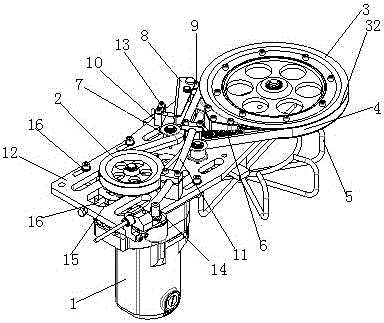
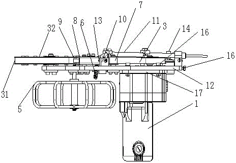
[0027] Such as Figure 1~2 As shown, a fully automatic threader includes a fixed plate 12, a motor 1, a synchronous pulley 3, and an adjustment mechanism; a motor is provided below the middle end of the fixed plate, and a motor plate 17 is provided on the motor. An adjustment plate 16 is fixed on the plate, and an adjustment plate hole is arranged on the fixing plate, and the adjustment plate can fit into the adjustment plate hole completely. A through hole is provided in the middle of the adjusting plate. The fixing plate and the adjusting plate are jointly provided with an adjusting channel, one end of the adjusting channel is located at the front side of the fixing plate, and the other end is adjacent to the through hole. The adjusting channel is provided with an adjusting member 16, the motor plate is provided with a through hole, the fixing plate is provided with a through hole corresponding to the through hole on the motor plate, and the adjusting member is penetrated in th


PUM


Abstract

The invention discloses a full-automatic threading device solving the problem that when a wire is threaded through a wire threading device in the prior art, the wire is prone to skidding and knotting. The full-automatic threading device comprises a motor, a fixing plate, a wire outlet mechanism and a wire inlet mechanism, and the motor is movably connected to the fixing plate and can move relative to the fixing plate. A shaft of the motor is connected with a fixing wheel, the fixing plate is further provided with a synchronous belt wheel, the synchronous belt wheel and the fixing wheel are sleeved with a synchronous belt, a gap is reserved between the synchronous belt and the synchronous belt wheel, and the wire outlet mechanism and the wire inlet mechanism are close to the synchronous belt wheel, and the wire winds around the synchronous belt wheel and enters the wire outlet mechanism after getting out of the wire inlet mechanism according to the positions. By means of the technical scheme, the problems in the prior art are well solved.

Description


Claims


Application Information

Patent Timeline
Owner 谢位强
Why Eureka
Try Eureka