Multifunctional mat
A multi-functional, cushion technology, applied in the direction of insulation layer, etc., can solve the problems of poor sound insulation effect, inconvenient installation, high cost, etc., and achieve the effect of enhancing air circulation function, improving dimensional stability, and improving quality of life
- Summary
- Abstract
- Description
- Claims
- Application Information
AI Technical Summary
Problems solved by technology
Method used
Image

Examples
Embodiment 1
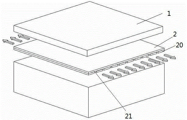
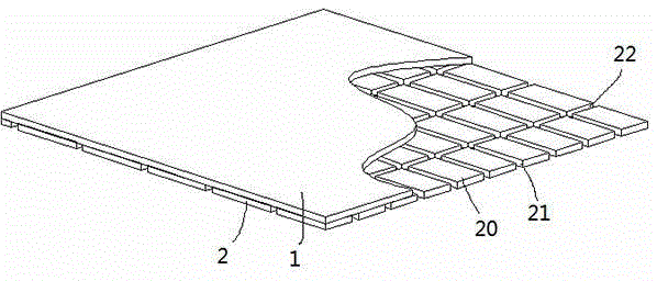
[0070] The minimum lateral distance between adjacent first sound insulation surfaces 21 between adjacent support units 20 is 0.5 mm; the distance between adjacent first sound insulation surfaces 21 of the same support unit 20 is 1 mm; the distance between the support units 20 and the sound insulation layer 1 is the farthest The minimum distance between the surface and the intersection of the sound insulation layer 1 and the first sound insulation surface 21 is 0.3 mm. The minimum longitudinal distance between adjacent second sound insulation surfaces 22 between adjacent support units 20 is 0.5 mm; the distance between adjacent second sound insulation surfaces 22 of the same support unit 20 is 150 mm; and the thickness of the sound insulation layer 1 is 1.5 mm.
[0071] The sound insulation layer 1 adopts a fully-open cell IXPE foamed sponge layer, and the support layer adopts a semi-open cell XPE foam material layer.
[0072] When installing and using, take the following steps:
[0073
Embodiment 2
[0089] The minimum lateral distance between adjacent first sound insulation surfaces 21 between adjacent support units 20 is 500 mm; the distance between adjacent first sound insulation surfaces 21 of the same support unit 20 is 1000 mm; the surface of the support unit 20 farthest from the sound insulation layer 1 The minimum distance to the intersection of the sound insulation layer 1 and the first sound insulation surface 21 is 39 mm.
[0090] The minimum lateral distance between adjacent first sound insulation surfaces 22 between adjacent support units 20 is 500 mm; the distance between adjacent first sound insulation surfaces 22 of the same support unit 20 is 1000 mm; and the thickness of the sound insulation layer 1 is 40 mm.
[0091] The sound insulation layer 1 is a closed-cell IXPE layer, and the support layer is a closed-cell polyethylene modified sound-insulating material layer.
[0092] The preparation method of polyethylene modified sound insulation material sequentially inc
Embodiment 3
[0102] The minimum lateral distance between adjacent first sound insulation surfaces 21 between adjacent support units 20 is 10 mm; the distance between adjacent first sound insulation surfaces 21 of the same support unit 20 is 50 mm; the surface of the support unit 20 farthest from the sound insulation layer 1 The minimum distance to the intersection of the sound insulation layer 1 and the first sound insulation surface 21 is 10 mm.
[0103] The minimum lateral distance between adjacent first sound insulation surfaces 22 between adjacent support units 20 is 200 mm; the distance between adjacent first sound insulation surfaces 22 of the same support unit 20 is 500 mm; and the thickness of the sound insulation layer 1 is 30 mm.
[0104] The sound insulation layer 1 is a closed cell polyethylene modified sound insulation material layer, and the support layer is a semi-open cell EPDM foamed sponge layer.
[0105] The preparation method of polyethylene modified sound insulation material seq
PUM
| Property | Measurement | Unit |
|---|---|---|
| Thickness | aaaaa | aaaaa |
| Thickness | aaaaa | aaaaa |
Abstract
Description
Claims
Application Information
 - R&D Engineer
- R&D Manager
- IP Professional
- Industry Leading Data Capabilities
- Powerful AI technology
- Patent DNA Extraction
Browse by: Latest US Patents, China's latest patents, Technical Efficacy Thesaurus, Application Domain, Technology Topic.
© 2024 PatSnap. All rights reserved.Legal|Privacy policy|Modern Slavery Act Transparency Statement|Sitemap