Wasted plastic steel wound polyethylene drainage pipe recovering device and technology

A waste polyethylene, recycling device technology, applied in the direction of pipeline laying and maintenance, pipe/pipe joints/pipe fittings, machinery and equipment, etc., can solve the problems of high cost, labor, low efficiency, etc., to reduce recycling costs, device design Simple, speed-up results

Active Publication Date: 2015-09-23
开源塑业科技(南通)有限公司
View PDF8 Cites 3 Cited by
  • Summary
  • Abstract
  • Description
  • Claims
  • Application Information

AI Technical Summary

Benefits of technology

This new technology simplifies its designs while still being effective at making it easier for users to operate safely with less effort or recovering from damage caused by external factors like firearms.

Problems solved by technology

Technological Problem: Different types of waste materials like buried ones can cause environmental issues when they enter waterways for various reasons including contamination caused by human activity, land use changes, leaks, etc., while disposers have difficulty separating these wastes into different categories based solely upon their properties. Existing methods involve creation of new pipings requiring significant effort and resources, making them expensive to reuse over again without being able to effectively recover any remaining useful material therein after usage.

Method used


Image

  • Wasted plastic steel wound polyethylene drainage pipe recovering device and technology
  • Wasted plastic steel wound polyethylene drainage pipe recovering device and technology
  • Wasted plastic steel wound polyethylene drainage pipe recovering device and technology

Examples


Embodiment Construction

[0020] In order to further illustrate and introduce the present invention, introduce below in conjunction with accompanying drawing of description:

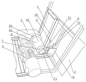
[0021] Refer to attached figure 1 , waste polyethylene plastic steel winding drainage pipe recovery device, it includes a frame 1, a feed partition 2, a feed port 3, a drive motor 4, a speed change gear box 5, a drum 6, and the frame 1 is a square Bracket, the upper end inside the bracket is equipped with a control box, the lower end inside the bracket is equipped with a drive motor 4, one end of the drive motor 4 is connected with a speed change gear box 5, and the speed change gear box 5 is installed on one side of the lower end of the inside of the bracket, and the other end of the speed change gear box 5 One end is connected with a drum 6, and one end of the drum 6 is fixedly connected to the gear box, and the other end of the drum 6 is supported by the support arm 7, and the feed separator 2 is installed between the brackets on


PUM


Abstract

The invention relates to a wasted plastic steel wound polyethylene drainage pipe recovering device and technology. The device comprises a machine frame, a feeding partition board, a feed inlet, a driving motor, a speed change gearbox and a rotary cylinder. A control box is arranged at the upper end of the interior of the support, the driving motor is installed at the lower end of the interior of the support, the speed change gearbox is connected to one end of the driving motor and located at one side of the lower end of the interior of the support, and the rotary cylinder is connected to the other end of the speed change gearbox; one end of the rotary cylinder is fixedly connected to the speed change gearbox, the other end of the rotary cylinder is supported by a supporting arm, the feeding partition board is installed between the two sides of the support and located at one side of the rotary cylinder, vertical reinforcing ribs are installed on the back side of the feeding partition board, and a baffle is welded to the lower ends of the vertical reinforcing ribs; the feed inlet is formed in the middle of the feeding partition board, and two stand columns are further installed between the feed inlet of the feeding partition board and the rotary cylinder and located at the inner side of the feed inlet. The device has the advantages of being simple in design, convenient to operate, safe, reliable, and capable of saving time, decreasing labor force, reducing recovery cost and improving working efficiency greatly.

Description


Claims


Application Information

Patent Timeline
Owner 开源塑业科技(南通)有限公司
Why Eureka
Try Eureka