Solid fuel combustion apparatus

A solid fuel and combustion device technology, applied in the field of solid fuel combustion, achieves the effects of orderly and controllable combustion, saving manpower and improving combustion efficiency

Inactive Publication Date: 2015-10-14
车战斌
View PDF5 Cites 4 Cited by
  • Summary
  • Abstract
  • Description
  • Claims
  • Application Information

AI Technical Summary

Problems solved by technology

[0019] The working principle of the combustion device of the solid fuel of the present invention is described as follows. During the combustion process, the volatile matter and the fixed carbon combustion of the fuel are all in the stockpile layer. Under the action of gravity, it automatically moves downwards and is gradually ignited by the combustion flame in the lower layer. New fuel is automatically added to the stockpiling layer from the feed port, and the fixed carbon combustion of the fuel in the lower layer provides the required heat for the volatile separation of the new fuel in the upper layer. , the replenishment rate of the new fuel depends on the combustion rate of the lower fuel, thus naturally realizing the matching of the volatile matter precipitation in the upper layer and the burning rate of the fixed carbon fuel, effectively solving the safety hazards existing in the existing hot blast stove due to the mismatch of the burning rate

Method used


Image

  • Solid fuel combustion apparatus
  • Solid fuel combustion apparatus
  • Solid fuel combustion apparatus

Examples


Example Embodiment

[0058] The technical solutions in the embodiments of the present invention will be clearly and completely described below in conjunction with the accompanying drawings in the embodiments of the present invention. Obviously, the described embodiments are only a part of the embodiments of the present invention, rather than all the embodiments. Based on the embodiments of the present invention, all other embodiments obtained by those of ordinary skill in the art without creative work shall fall within the protection scope of the present invention.

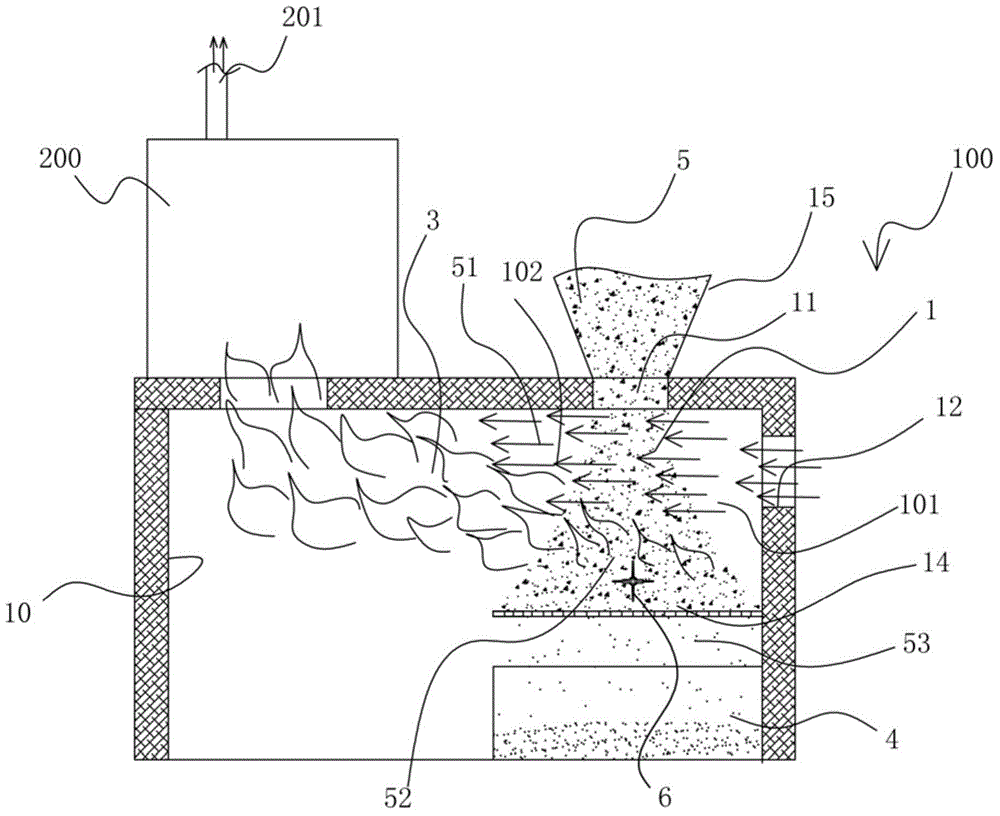
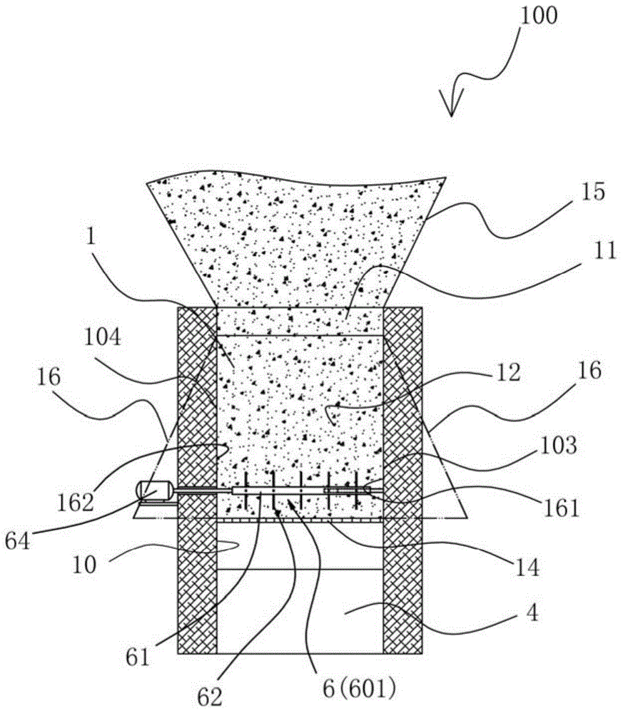
[0059] Such as Figure 2 to Figure 4 as well as Picture 10 As shown, a solid fuel combustion device 100 of the present invention includes a furnace 10 on which an air inlet 12 and a solid fuel inlet 11 are provided. The feed port 11 is provided at the top of the furnace 10, and a grate 14 is provided in the furnace 10 corresponding to the feed port 11 to receive the solid fuel 5 entering from the feed port 11. The solid fuel 5 is at the fee


PUM


Abstract

Disclosed is a combustion device (100) for solid fuels. An air inlet side (101) is formed above a furnace grate (14) in a furnace (10) and on one side of a fuel stocking layer (1) of the combustion device (100), a combustion side (102) is formed in the furnace (10) on the other side opposite to the fuel stocking layer (1); a shuffle mechanism (6) is arranged in the fuel stocking layer (1) above the furnace grate (14) for receiving the solid fuels, and the fuels in a combustion state can be shuffled by controlling the movement of the shuffle mechanism (6), which is beneficial for discharging ash.

Description


Claims


Application Information

Patent Timeline
Owner 车战斌
Why Eureka
Try Eureka