High-efficiency maintenance device for oil pipe

A high-efficiency technology for oil pipes, applied in the field of high-efficiency maintenance devices for oil pipes, can solve the problems of heavy materials, heavy workload, and long maintenance methods, and achieve the effect of saving operation time and reducing workload.

Inactive Publication Date: 2015-11-04
CHINA NAT OFFSHORE OIL CORP +1
View PDF7 Cites 0 Cited by
  • Summary
  • Abstract
  • Description
  • Claims
  • Application Information

AI Technical Summary

Problems solved by technology

The mud used in high-temperature and high-pressure wells has a high specific gravity, and there are relatively many weighting materials in the mud. There are debris on

Method used


Image

  • High-efficiency maintenance device for oil pipe
  • High-efficiency maintenance device for oil pipe

Examples


Embodiment Construction

[0018] In order to enable those skilled in the art to better understand the technical solution of the present invention, the present invention will be described in further detail below in conjunction with the accompanying drawings and specific embodiments. And the features in the embodiments can be combined with each other.

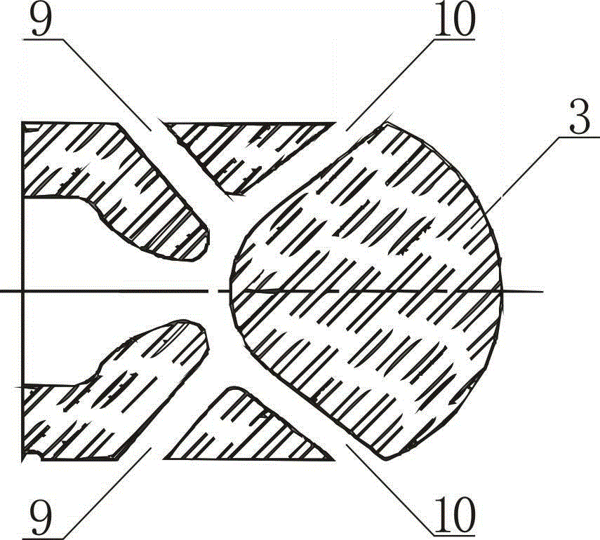
[0019] Such as figure 1 As shown, the high-efficiency oil pipe maintenance device includes a booster pump 1, a hose 2 and a nozzle 3. The booster pump can provide an electric drive pump with a pressure of 20MPa, a displacement of 170L / min, and a driving power of 75kw.

[0020] It also includes a drum 4 , a base 5 and a fixed frame 6 , the drum 4 and the booster pump 1 are both arranged on the base 5 , and the hose 2 is wound on the drum 4 . The base 5 is arranged on a fixed frame 6 , and the fixed frame 6 is provided with a suspension ring 7 . During work, shower nozzle 3 stretches in the oil pipe 8 that is maintained.

[0021] Such as figure 2 As sho


PUM


Abstract

The invention discloses a high-efficiency maintenance device for an oil pipe. The high-efficiency maintenance device for the oil pipe comprises a booster pump, a hose and a spray head, a flushing spray orifice set is arranged on the front side portion of the spray head, a rear thrust spray orifice set is arranged on the rear side portion of the spray head, the booster pump compresses water, the compressed water flows to the spray head through the hose, the compressed water is sprayed through the flushing spray orifice set of the spray head to the oblique front portion to flush the inner wall of the maintained oil pipe, the compressed water is further sprayed through the rear thrust spray orifice set to the oblique rear portion to the inner wall of the maintained oil pipe to drive the spray head to move forward in the maintained oil pipe. The flushing spray orifice set is composed of four spray orifices with an inclined angle of 45 degrees, and the rear thrust spray orifice set is composed of six spray orifices with an inclined angle of 60 degrees. By means of the high-efficiency maintenance device for the oil pipe, high-efficiency maintenance can be rapidly conducted on a high-temperature, high-pressure and air-tightness oil pipe pulled out on site, and the requirements for making the oil pipe placed into a well again can be met; on-site operation time is saved, the workload of on-site staff is reduced, and therefore it is guaranteed that follow-up operations can be completed smoothly.

Description


Claims


Application Information

Patent Timeline
Owner CHINA NAT OFFSHORE OIL CORP
Why Eureka
Try Eureka