Device and method for segregating unwanted items from a stream of bulk material

A technology for bulk materials and separation devices, applied in the field of metal devices, which can solve problems such as interruption of production process, film tearing, impact, etc.

Inactive Publication Date: 2015-12-16
LINDAUER DORNIER GMBH
View PDF8 Cites 4 Cited by
  • Summary
  • Abstract
  • Description
  • Claims
  • Application Information

AI Technical Summary

Benefits of technology

The technical effect of this patented technology described in this patents relates to improving the performance and efficiency of separators in industrial processes like feeders and conveyance systems. By divining the incoming bulk material into different paths along separate conduction chambers, any blocked areas will fall back downstream while others continue forward. Additionally, there is a design where certain connections within the separation units allow for equal delivery rates across all the branches of the path. These feature improve the overall quality control of the processed product delivered over time. Overall, this innovation enhances the functionality and reliability of the separator system.

Problems solved by technology

Technological Problem: Current methods involve dislodging soil that contains metals such as iron oxide, zinc sulfate, lead chromium, silver, etc., causing damages on devices like injection machines and other industrial machining tools. Existing techniques have limitations in effectively preventing these types of harm caused by residual impurities in the feedstock stream being treated without affecting their quality.

Method used


Image

  • Device and method for segregating unwanted items from a stream of bulk material
  • Device and method for segregating unwanted items from a stream of bulk material
  • Device and method for segregating unwanted items from a stream of bulk material

Examples


Embodiment Construction

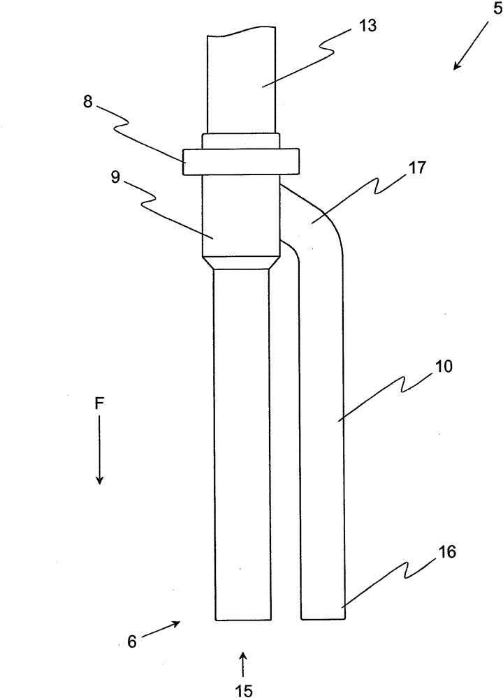
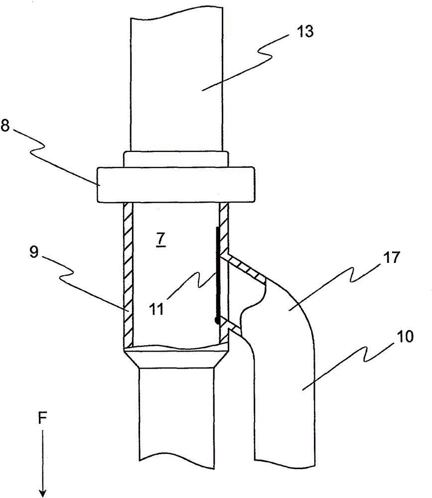
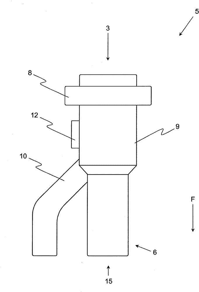
[0048] Figures 1 to 3 The basic structure of a known device for separating dirt 1 from a bulk material flow is shown. These devices are always used if the bulk material 4 (eg plastic pellets) to be processed in a subsequent production plant (eg extruder) is to be monitored for dirt 1 and removed from the bulk material flow. In particular in the case of plastic granules, the contaminants 1 can be metal fragments which can cause damage to the equipment for processing the plastic granules and / or interrupt the corresponding production process.

[0049] In order to prevent this, the device shown has in the shown case an inlet opening 3 through which the bulk material flow can be introduced into the device. Bulk material 4 may, for example, come from only image 3 The bulk material input 2 indicated in , which can be formed, for example, by a bulk material tank, preferably delivers a constant mass flow of the bulk material via a corresponding metering device.

[0050] On the way,


PUM


Abstract

The invention relates to a device for segregating unwanted items (1) from a stream of bulk material, wherein the device has at least one inlet opening (3) for the bulk material (4), which can be connected to a bulk material feed (2), a segregating unit (5), which is arranged downstream of the inlet opening (3) in a transporting direction (F) of the stream of bulk material, and also at least one outlet (6) for the bulk material (4) freed of unwanted items (1) with the aid of the segregating unit (5), arranged downstream of the segregating unit (5) in said transporting direction (F). It is proposed according to the invention that the segregating unit (5) has at least two transporting channels (7) arranged in parallel and branching away from the inlet opening (3), wherein the transporting channels (7) can respectively be passed by a partial stream of bulk material branching off from the stream of bulk material flowing in by way of the inlet opening (3), and wherein each of the transporting channels (7) is assigned at least one detector (8) for the detection of unwanted items (1) and a separating device (9), with the aid of which the partial stream of bulk material passing the respective transporting channel (7) can be diverted into a system of disposal channels (10). A description is also given of a method for segregating unwanted items (1) from a stream of bulk material with the aid of a segregating unit (5), which is distinguished by the fact that the stream of bulk material is divided into at least two partial streams of bulk material before or within the segregating unit (5), wherein each partial stream of bulk material is monitored individually with regard to the presence of unwanted items (1) with the aid of a separate detector (8) of the detector arrangement (18), and wherein only the partial stream of bulk material that has an unwanted item (1) is diverted into a system of disposal channels (10).

Description


Claims


Application Information

Patent Timeline
Owner LINDAUER DORNIER GMBH
Why Eureka
Try Eureka