Driven wheel structure

A passive wheel and passive technology, applied in the field of manipulators, can solve the problems of inconvenient adjustment, troublesome assembly and disassembly of passive wheels, etc.

Inactive Publication Date: 2015-12-30
DONGGUAN SANNIAN INTELLIGENT TECH CO LTD
View PDF24 Cites 0 Cited by
  • Summary
  • Abstract
  • Description
  • Claims
  • Application Information

AI Technical Summary

Benefits of technology

The present invent describes a mechanism used by vehicles' wheels called drive tires or axles. These mechanisms have a hole inside them where they can fit other components like cables (electric wiring). This allows these parts to move freely within it without interferring with each others. It also makes maintenance easier because there will always be space between certain areas during assembly.

Problems solved by technology

This patented describes how robots use their own power sources like motors to operate without being controlled manually. However, current methods require manual intervention during installation/disconnection procedures due to its complexity. There needs a better solution to this problem.

Method used


Image

  • Driven wheel structure
  • Driven wheel structure
  • Driven wheel structure

Examples


Embodiment Construction

[0022] In order to describe the technical content and structural features of the present invention in detail, further description will be given below in conjunction with the implementation and accompanying drawings.

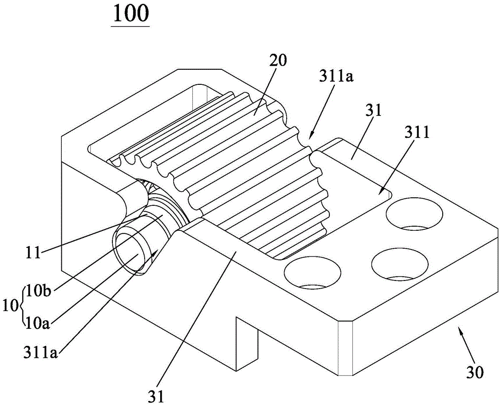
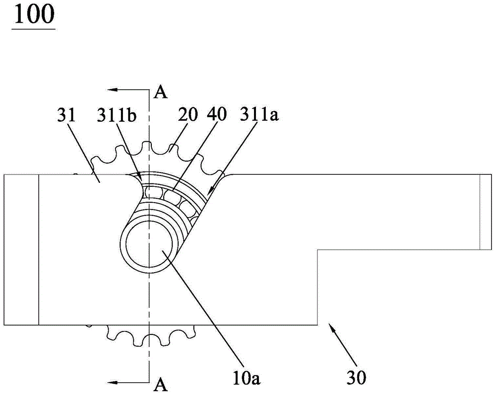
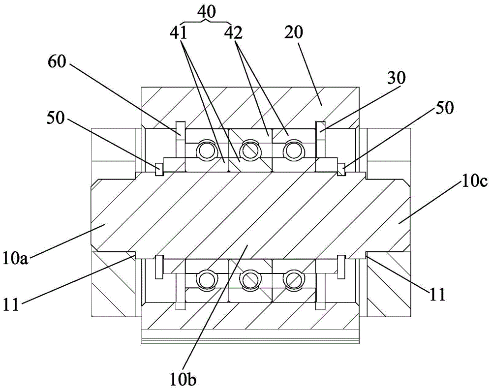
[0023] see Figure 1 to Figure 3 , The driven wheel structure 100 of the present invention includes a fixed shaft 10 , a driven wheel 20 and a support seat 30 of a hollow structure. The hollow structure penetrates the support base 30 along the first direction and forms an accommodating cavity 31 for the passive wheel 20 to be accommodated; specifically, in this embodiment, the hollow structure penetrates the support base 30 from bottom to top. , so the first direction in this embodiment refers to the direction from bottom to top of the support seat 30, of course, in other embodiments, the first direction can also refer to the direction from top to bottom of the support seat 30, or the direction of the support seat 30 from the front The direction to the back or from


PUM


Abstract

The invention discloses a driven wheel structure, comprising a fixed shaft, a driven wheel and a supporting seat of a hollow structure, wherein the hollow structure penetrates runs through the supporting seat along a first direction and forms a containing cavity for containing the driven wheel, and two opposite cavity walls of the containing cavity are respectively provided with an inclined slot which is communicated with the containing cavity and inclines relative to the first direction. The fixed shaft is arranged on the driven wheel in a penetrating way, and a first end and a second end of the fixed shaft extend out of the driven wheel along different directions; when the driven wheel moves to the first end and the second end of the fixed shaft along a direction opposite to the first direction, so as to be arranged at the positions of slot openings of the corresponding inclined slots, the fixed shaft slides along the inclined slots and enables the driven wheel to be installed into the containing cavity, thus facilitating assembling and disassembling of the driven wheel and also facilitating the adjustment of adjusting the driven wheel.

Description


Claims


Application Information

Patent Timeline
Owner DONGGUAN SANNIAN INTELLIGENT TECH CO LTD
Why Eureka
Try Eureka