Nut dismounting tool

A technology for tools and nuts, which is applied in the field of nut disassembly and assembly tools, can solve problems such as low efficiency, achieve the effect of avoiding inconvenience and improving disassembly and assembly efficiency

Inactive Publication Date: 2016-01-13
LAIWU IRON & STEEL GRP
View PDF6 Cites 0 Cited by
  • Summary
  • Abstract
  • Description
  • Claims
  • Application Information

AI Technical Summary

Benefits of technology

The inventor's new type of tools called an electrical screw dismantlement tool uses two parts - one being attached atop another when they are lifted up or down during use. When this happens, there will just have to align these components correctly before rotating them around again. These tools make it easier than traditional methods like regular ones because they don’t require any extra steps after each step. They improve workplace safety while still providing effective ways to remove nuts without having hands touch their surface.

Problems solved by technology

In this patented technical solution for replacing or rebuilding sectors on a slabs during production, there was no convenient way to remove bolts from certain parts without having them fall out easily due to their small size. Therefore, it resulted in lower maintenance costs compared to traditional methods like screws.

Method used


Image

  • Nut dismounting tool
  • Nut dismounting tool
  • Nut dismounting tool

Examples


Embodiment Construction

[0038] In order to enable those skilled in the art to better understand the technical solutions in the present invention, the technical solutions in the embodiments of the present invention will be clearly and completely described below in conjunction with the drawings in the embodiments of the present invention. Obviously, the described The embodiments are only some of the embodiments of the present invention, not all of them. Based on the embodiments of the present invention, all other embodiments obtained by persons of ordinary skill in the art without making creative efforts shall fall within the protection scope of the present invention.

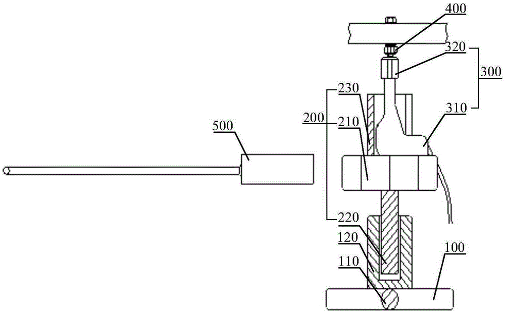
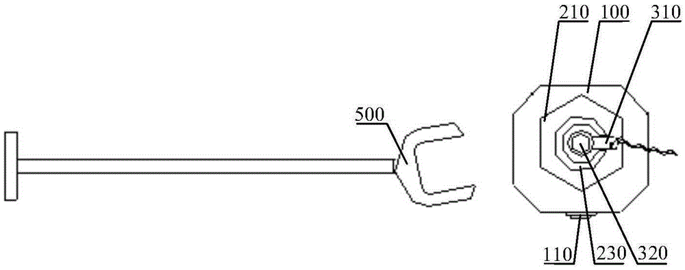
[0039] Please refer to figure 1 with 2 , the embodiment of the present invention provides a nut removal tool. The nut removal tool provided includes a base, a lifting part 200 and an electric wrench 300 .

[0040] Wherein, the base is the basis of the entire nut dismounting tool, and is used to provide an installation basis for other pa


PUM


Abstract

The invention provides a nut dismounting tool. The nut dismounting tool comprises a base, an up-and-down part (200) capable of rising and falling relative to the base, and an electric wrench (300) arranged on the up-and-down part (200), wherein the electric wrench (300) comprises a wrench body (310) and a knob dismounting head (320) for dismounting a nut (400); the wrench body (310) is positioned and matched with the up-and-down part (200) in a direction of rotation of the knob dismounting head (320). The nut dismounting tool is capable of solving the problem of relatively low efficiency of dismounting the nut in a narrow space.

Description


Claims


Application Information

Patent Timeline
Owner LAIWU IRON & STEEL GRP
Why Eureka
Try Eureka